• Skip to main content
  • Skip to primary sidebar

Making Easy Circuits

Learn and build electronic circuits

You are here: Home / Datasheets / 2N3904 Datasheet [40V 200mA NPN Transistor]

2N3904 Datasheet [40V 200mA NPN Transistor]

Last Updated on February 21, 2023 by admin Leave a Comment

The post discusses the complete datasheet of the transistor 2N3904.

Electrical Characteristics (TJ = 25°C unless otherwise noted)

  • Collector-Emitter Breakdown Voltage (V(BR)CEO): 40-60V
  • Collector-Base Breakdown Voltage (V(BR)CBO): 60V
  • Emitter-Base Breakdown Voltage (V(BR)EBO): 6V
  • Collector-Emitter Saturation Voltage (VCE(sat)): 0.2-0.3V
  • Base-Emitter On Voltage (VBE(on)): 0.65-0.85V
  • DC Current Gain (hFE): 100-300
  • Collector Cutoff Current (ICBO): 50nA max
  • Emitter Cutoff Current (IEBO): 50nA max

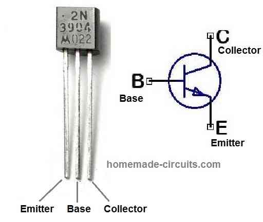
Pinout Configuration

The following image provides the pinout details and configuration for the transistor 2N3904.

Absolute Maximum Ratings

  • Collector-Emitter Voltage (VCEO): 40V
  • Collector-Base Voltage (VCBO): 60V
  • Emitter-Base Voltage (VEBO): 6V
  • Collector Current (IC): 200mA
  • Base Current (IB): 20mA
  • Power Dissipation (Pd): 625mW

Miscellaneous Information

  • The 2N3904 is a general-purpose NPN bipolar junction transistor (BJT).
  • Its package type is TO-92, which is a popular small signal package used for transistors and other electronic components.
  • The maximum power dissipation of the transistor is 625mW, which means it can handle up to 625mW of power before it begins to overheat.
  • The maximum collector current of the transistor is 200mA, which means that it can handle up to 200mA of current flowing through the collector terminal.
  • The maximum collector-emitter voltage is 40V, which means that the transistor can handle up to 40V between the collector and emitter terminals before it breaks down.
  • The DC current gain of the transistor is typically between 100 and 300, which means that the current flowing through the collector is amplified by a factor of 100 to 300 times the current flowing through the base terminal.
  • The transistor can be used in a wide range of applications, including amplification, switching, and oscillation. Its low cost, small size, and versatility make it a popular choice for hobbyists and professionals alike.

You'll also like:

  • 1.  Rectifier Diode PIV, IF Explained
  • 2.  List of all Commonly used Transistors (BJT)
  • 3.  2N3906 Datasheet [40V, 200 mA PNP Transistor]
  • 4.  LF351 Op-Amp IC : Datasheet, Pin Details, Application Circuits
  • 5.  Understanding IC 4043 Pinouts, Datasheet
  • 6.  TL431 Circuits and Datasheet

About admin

Reader Interactions

Leave a Reply Cancel reply

Your email address will not be published. Required fields are marked *

Primary Sidebar

Categories

  • 3 Phase (4)
  • 8051 Microcontroller (1)
  • Alarm (37)
  • Amplifier (41)
  • Amusement (32)
  • Arduino (9)
  • Audio (50)
  • Automation (5)
  • Battery Chargers (47)
  • Bicycle Projects (2)
  • Bluetooth (3)
  • Capacitor (2)
  • Car Electronics (24)
  • Cellphone (7)
  • Datasheets (8)
  • Detector (32)
  • Electrical (15)
  • Emergency Light (8)
  • Free Energy (3)
  • Gadgets (10)
  • High Voltage (13)
  • Hobby Projects (30)
  • IC 555 Circuits (5)
  • Ignition Circuits (2)
  • Indicators (46)
  • Infrared (6)
  • Inverter (23)
  • LED Projects (49)
  • Light effect (19)
  • Medical (7)
  • Meter and Tester Circuits (32)
  • Motor Driver (16)
  • Motorcycle Projects (2)
  • New Circuits (25)
  • Oscillators (26)
  • Power supply (40)
  • Protection Circuits (26)
  • PWM (9)
  • Remote Control (16)
  • Security Circuit (14)
  • Sensors (34)
  • Signal Processor (23)
  • SMPS (12)
  • Solar (43)
  • SSR (3)
  • Temperature Controller (18)
  • Timer (23)
  • Transformerless (9)
  • Transmitters (11)
  • Tutorials (36)
  • UPS (2)
  • Voltage Regulators (49)
  • Water Control (8)
  • Water Sensor (13)
  • Home
  • Privacy Policy
  • Contact
  • Disclaimer
  • Copyright

© 2023 · Making Easy Circuits