This specific 3.3V 2amp SMPS Circuit for LEDs was originally designed to power the digital cameras. Current usage of this camera is approximately 0.6 A and 1.3 A maximum (flash pulse).
For this reason, it undoubtedly wants a traditional linear supply with eg LM317, however the efficiency could be just around 30% along with a heavy transformer and stabilizer with a substantially warming heatsink.
This switching power supply is actually a considerably more sophisticated alternative. On the net there could be quite a few schematics of switching power supplies using 3842, additional transistors or may be plenty of avoidable parts.
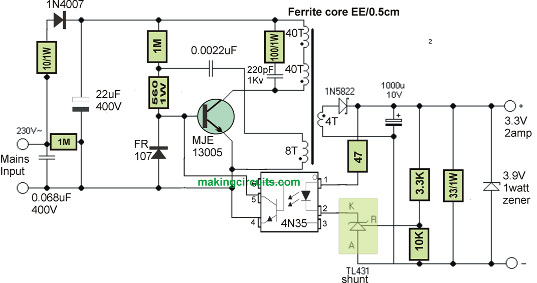
The diagram beneath demonstrates an easy to use schematic of the little switching power supply having a solitary transistor and optocoupler.
Switching power supply with no optocoupler with all the roundabout stabilization might be much more easy, nevertheless output voltage will not be steady more than enough.
This 3.3V 2amp SMPS Circuit for LEDs is actually a flyback converter. The principle is straightforward: Right after switching ON the mains input the 1M 1W base resistor to a certain extent starts up the transistor.
This encourages the positive voltage around the auxiliary winding (8 turns) and the transistor to conduct hard fully.
As soon as the capacitor 2n2 becomes discharged, The transistor is usually switched off and the voltage stimulated for the secondary will be charging the filtration electrolytic capacitor.
As soon as the 2n2 capacitor becomes recharged yet again, the transistor re-opens and almost everything is normally repeated. Once the preferred voltage chosen by resistive divider 3k3 and 10k starts up the TL431 circuit, the LED inside the optocoupler sets out to illuminate and a phototransistor switches ON and limits the current for the transistor base.
This action instantly lowers the PWM duty cycle and cuts down power transfered to the transformer.
This procedure of stabilization works extremely well, the full load voltage lowers by a maximum of 0.01 V. This specific switching power supply finds it difficult to support no load condition, hence the output dummy load resistor 33R is associated with do away with this issue.
Zener diode shields the mains powered devices prior to overvoltage just in the case of malfunction of stabilization. As an alternative, you can utilize other ways of overvoltage security, including the one having SCR. 68n capacitor makes certain EMI interference is suppressed, resistance 10R cuts down the surge current any time switched on.
2n2 capacitor experimentation may change the working frequency. Printed circuit board needs to be specified in order that the primary (mains) and the secondary portion were definitely away from each other significantly enough.
The transformer can be built on an EE ferrite core using an effective cross section 0.5 cm2. Initially, the 1st half of primary turns are wrapped, ie 40 turns.
The wire carries a diameter of approximately 0.2 - 0.3 mm. Subsequently a minimum of 8 layers of insulating tape should be wrapped. Next comes the secondary coils.
For basic safety I applied wire having heavy insulation, which using just 4 turns is not really a difficulty, accompanied by 8 layers of insulation strapping. Additionally, for the auxiliary turns 8 turns are wound, while using the very same wire as used for the primary.
Next, apply insulating layer, which might not really be as robust as earlier. Ultimately, additional 40 turns of primary may be wound. Followed by a few cellular levels of insulation tape.
Between the core faces is inserted a single coating of insulating tape to create an air gap in order to avoid core saturation. Eventually, the asssembled core is sealed with glue.
This 3.3V 2amp SMPS Circuit for LEDs can easily naturally be altered for diverse output voltages, simply by modifying the amount of secondary turns (roughly 1 turn compares to 1V) resistor 39R is altered by about 10R for every single 1V and sits firmly the output voltage be modified by modifying the resistor 3k3 in order that at the expected voltage the potential divider provides 2.5 V at input of TL431.
Zener diode is usually decided on somewhat higher than the desired output voltage. Rectifier diode need to have a reverse voltage no less than Eight times bigger than the output voltage.
For greater voltages, as a result, change Schottky diode through fast recovery diode for the reason that Schottky diodes possess usually reduced rated reverse voltage. Needless to say, the output electrolyte should be specified for the satisfactory voltage.
What will be maximum power that can be extracted from above circuit.
multiply output volt with amp
Can i replace tlp431 by 3.3v zener
try 4.7V zener
Why half main turns 40 are wounded at the end?
it is set as per the frequency of the primary side
I want 24v/1a .. how can I modify this circuit for that?
use 32 turns for the secondary winding, and adjust 3.3k resistor until 24V is set..and change the 47 ohm to 470 ohms
whats the modification to get 12v 1a output
increase the number of turns at the secondary to 10 turns, remove the 3.9V zener and adjust the 10K/3.3k resistor for exact 12v output