This whole thing is about this seriously awesome battery charger circuit, right? It is not just any old charger, its like a super-smart, automatic, one-stop-shop kind of deal.
And the coolest part is, you can totally customize it in a bunch of different ways to make it work exactly how you want it to, no matter what kind of batteries you are dealing with or what crazy applications you've got in mind.
Now this little circuit we're talking about can charge basically any kind of battery you can think of, from those tiny 1.5V ones all the way up to the big boys at 24V. All you got to do is set a little preset and, you' are good to go.
So how does this whole magical contraption actually work? Well, let me break it down for you especially when we're talking about that LM3915 IC which is like the brains of the operation:
The Main Feature
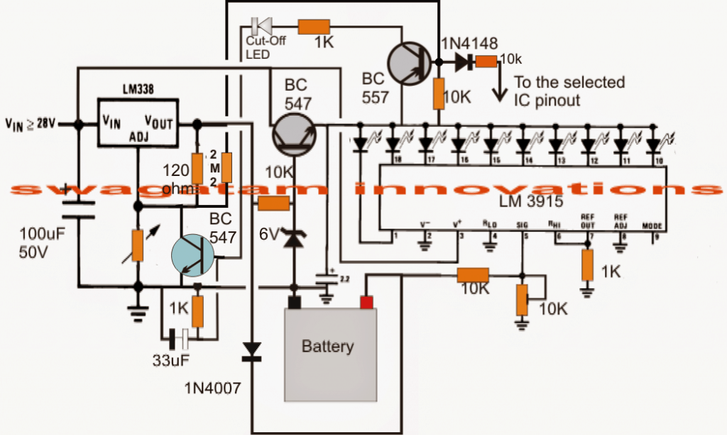
So the heart and soul of this circuit is this chip called the LM3915. Think of it like a super fancy voltage display. It is got like ten little outputs that are all lined up in a row, and they light up one after the other, kind of like a progress bar as the voltage goes up on this one special pin, pin number 5.
So basically each light that comes on is like telling you exactly how charged your battery is at that very moment which is pretty darn neat if you ask me. It visually represents the charge level.
Getting Everything Set Up Just Right:
Now a 10K preset which is basically just a little knob that you can turn to adjust things. You got to set this thing depending on the voltage of the particular battery you're trying to charge. So as your battery starts sucking up electricity and charging up, these LEDs start lighting up in a nice, orderly fashion, showing you exactly how much juice the battery's got.
And then when that very last LED finally decides to light up, that means your battery is completely full. But that's not all! When that last LED lights up, it triggers an SCR, which is like a little switch that shuts off the charging process completely. And it stays off too until you come along and reset the whole system.
Keeping the Voltage Nice and Steady:
We've also got this part of the circuit with the LM338 which is your run-of-the-mill, garden-variety voltage regulator. You have to fiddle with another one of those preset knobs to match the full charge limit of whatever battery you're working with.
And then there is this transistor the BC547 which is there to give a nice steady 3V to all those LEDs just to make sure they do not go haywire and burn out or something. It keeps everything nice and stable.
The Ultimate Cut-Off Switcher:
Okay so here' is where things get really clever. There is this other transistor, the BC557 and it just sits there, doing absolutely nothing until that very last LED finally lights up telling us that the battery is totally full. But as soon as that happens The BC557 wakes up and turns on which then triggers that SCR thing we were talking about earlier.
And the SCR in turn grounds the ADJ pin of the LM338 which is like cutting the power cord to the battery. That shuts off the flow of electricity completely and stops the battery from getting overcharged which is a super important thing because nobody wants a battery that is gonna explode right?
So How Do We Actually Get This Thing Up and Running?
This circuit is pretty versatile so it can handle batteries of all shapes and sizes, from those tiny little 1.5V guys all the way up to the beefy 24V ones. So let us just pretend for a second that you're trying to charge a regular old 6V battery okay? Well the full charge voltage for that battery would be somewhere around 7V just to give it that extra little bit of juice it needs.
The very first thing you got to do is not connect the battery. I know it sounds weird but trust me on this one. And you also got to disconnect that SCR gate from the BC557 thingy.
Voltage Adjustment Time:
Alright now you're gonna apply a higher DC voltage to the LM338. Something like 9V or 12V should do the trick. Then you are gonna grab that 10K preset knob that is hanging out under the LM338 and start twisting it until you get a nice, steady 7V output at those battery terminal points.
LED Fine-Tuning:
Now You are gonna grab that other 10K preset knob, the one that's under the LM3915 and start tweaking with it until that very last LED just barely flickers on when it hits 7V. That means you have got it dialed in just right.
Reconnecting Everything:
now that you've got everything adjusted perfectly, you can go ahead and reconnect that SCR gate just like it shows in the circuit diagram. And that's it! You're all done!
Now while the thing is charging up, each LED is gonna represent about 0.7V (because 7V divided by 10 LEDs is 0.7V, duh). So if your batterys sitting at around 5V you will see the 7th LED light up. And as the voltage slowly creeps up by 0.7V the next LED will light up and so on and so forth until finally that last LED kicks in and shuts the whole shebang down.
But There's More! (Alternate Setup for 3V to 12V Batteries)
Now if you wanna get really fancy and make this circuit work with a whole range of batteries from 3V all the way up to 12V here's what you got to do. You're gonna adjust that LM3915 preset knob so that the last LED barely lights up when it hits 14.4V. In that case each LED is gonna represent about 1.4V (because 14.4V divided by 10 LEDs is 1.4V, math!).
So if you are charging a 6V battery the LED that is gonna light up when it' is fully charged is the 5th one (because 7V divided by 1.4V is 5).
And if you're charging a 9V battery it's gonna be the 6th LED (because around 9V divided by 1.4V is like, 6-ish).
All you got to do is connect the base of that BC557 transistor to the right LED pin and you are done!
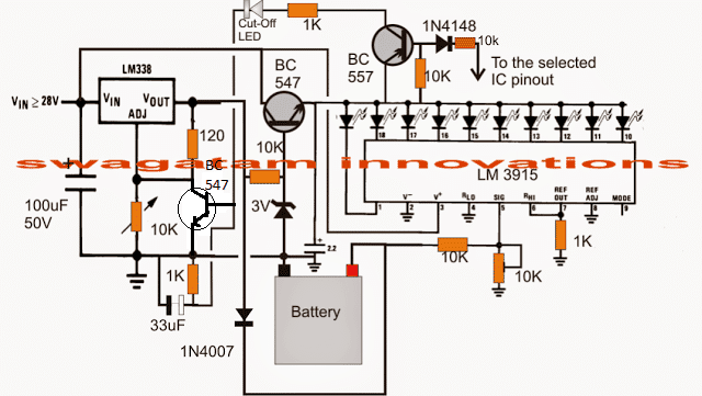
Circuit Diagram

Transistor latching in place of SCR
The next circuit, which uses a transistor latch, could be used should the SCR in the preceding circuit is ineffective:
For an Operation That Is Automatically ON/OFF
You may try altering the schematic in a particular way if you would like the versatile battery charger circuit mentioned above to turn off the charger once the battery arrives at the full charge limit, turn on the charging right away when the battery begins to fall below the full charge boundary, and afterwards keep going flip flopping at that limit range:
Leave a Reply