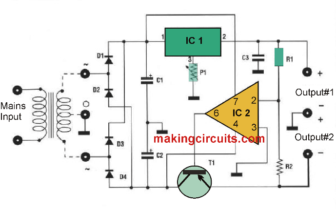
The concurrent adjustment of the two outputs enables it to be used to supply integrated circuits and other kinds of devices that require a dual supply of between + -5 and 12 volts.
Circuit Description
Additionally it is achievable to supply TTL logic circuits, integrated circuits and every other unit in which the working voltage is between 5 and 12 volts utilizing a single output.

Using the two outputs in series, a power supply with a voltage varying between 10 and 24 Volts can be formed
It should not be overlooked that regardless of the type of usage possible, it should not go beyond the consumption of 500-600 mA. Because of its functioning, you must hook up to the input a transformer with a secondary of 15 Volts which could deliver a current of at least 500 mA.
For the assemblage of the components, cautiously stick to the layout diagram.

PCB design for the +/-5V to 12V Adjustable Power Supply Circuit

Component supply configuration adjustable ± 5 to 12 Volts 500 mA
circuit board power supply adjustable ± 5 to 12 Volts 500 mA
ELECTRONIC COMPONENT LIST:
All resistors are
1/4 watt unless otherwise stated.
R1 = 4.7K
R2 = 4.7K
Pl = 2.2K potentA.
Cl = 1000uF25Velec.
C2 = 1000uF/25Velec.
C3 = 0.1 uF ceramic.
D1-1N4001 ... 7
D2 = 1N4001 ... 7
D3-1N4001 ... 7
D4 = 1N4001 ... 7
T1 = TIP32
1C1 = 7805
IC2 = 741
1 8-pin support.
2 Heat sink
Leave a Reply