• Skip to main content
  • Skip to primary sidebar

Making Easy Circuits

Learn and build electronic circuits

You are here: Home / Lights and Lamps / 6v DC 20 watt Florescent Lamp Driver Circuit

6v DC 20 watt Florescent Lamp Driver Circuit

Last Updated on November 27, 2024 by Admin 9 Comments

In many rather daily occasions many of us may possibly be caught up over a power outage conditions (no electrical power on evenings). Ooh how extremely annoying evening ! ... absolutely no view of anything whatsoever and youngsters are moping and crying ... oh yea may well ... my oh my may perhaps.

Therefore for just a few moment - last week; I actually tried a defective personal computer power accessory unit, disassemble this and apply certain decent component to this and connect and developed to build a 6v DC 20 watt Florescent Lamp Driver Circuit

This specific device meant to generate a 15 watts fl lamp illumination originating from a defective economical CFL - which usually not necessarily difficult and could be located within our residence.

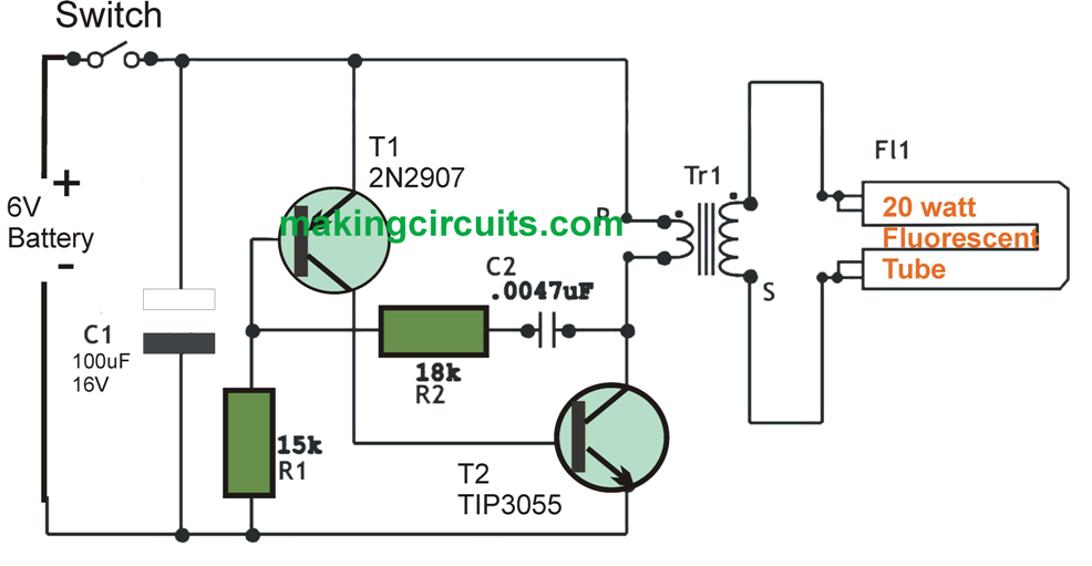
In this article you will find the schematic diagram :

6V 20 watt fluorescent driver circuit

PART LIST =

R1 = 15K Ohm / 0.5W
R2 = 22K Ohm / 0.5W
C1 = 100uF / 16V
C2 = 0.0047uF / 4n7F / 4.7KpF
T1 = 2N2907/ any 500mW PnP General Purpose Transistor
T2 = TIP3055 / or any TO220 3A NpN Switch Mode Transistor
Tr1 = Ferit Core Transformer. 15w 0.8mm magnet wire Primary winding and 300w 0.5mm magnet wire Secondary winding (rewinding from cpu psu transformer ! ).
S1 = Switch
Bat = 6V 4AH cell gel batery

Basicaly this 6v DC 20 watt Florescent Lamp Driver Circuit is a self-oscillating on ~ 25-35 KHz. with R2 and C2 as frequency dependen parts.

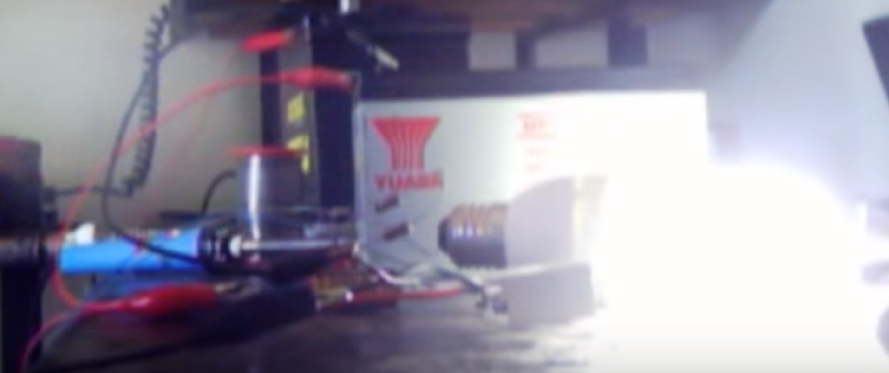
Here photo unit I've built :


6V CFL

and one more image of the unit energizing a 15 watts cfl lamp portion only. Observe how brilliant the cfl light possess using just 6V battery cell gel ! :


6V CFL

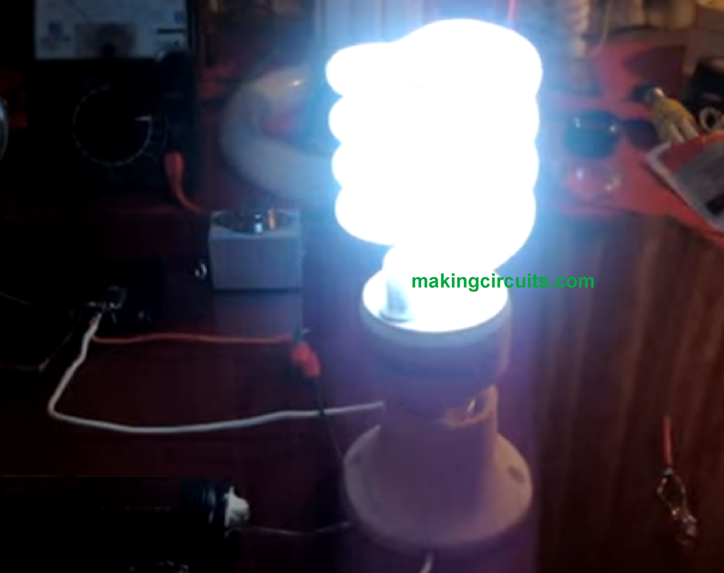
With around 100mA usage this particular device can function for approximately several hours before the battery may decrease it voltage to ~ Three volts.

WARNING =
THIS DEVICE CAN EASILY DEVELOP SUBSTANTIAL VOLTAGES WITHIN THE SECONDARY WINDING OF THE TRANSFORMER ! NEVER EVER TOUCH WHILE THE BATTERY IS ATTACHED WITH THE DEVICE ! WORK WITH EXTREME CAUTION !

You'll also like:

  • 1.  How to Build a Energy Saving Automatic LED Light Controller Circuit
  • 2.  Car Chasing LED Arrow Turn Signal Indicator Circuit
  • 3.  How to Build a 32V, 3 Amp LED Driver Circuit
  • 4.  220V Compact Tube Light Circuit using LEDs
  • 5.  How to Generate Infrared LED Flood Light
  • 6.  Cheap yet Accurate Automatic Street Light Circuit: Build it now

About Admin

Hey friends, Thanks a bunch for stopping by this site! I am an engineer with a Bachelor of Engineering in Electronics and Telecommunication. One of my passions is gathering information from all sorts of electronics books and tutorials. I then take that information and compile it into a language that is super easy to understand. My goal is to make those complex electronics circuit concepts and technical terms much more accessible for all the new and budding electronics engineers out there. I can also design customized circuit diagrams as required by the users.
If you have any questions related to this field, please do not hesitate to drop a comment! I am always here and ready to help you out with any queries you might have. I cannot wait to hear from you!

Reader Interactions

Comments

  1. Al Pace says

    December 19, 2022 at 1:53 pm

    What is the output voltage? am I right to assume it’s 12/15vdc?

    Reply
    • admin says

      January 1, 2023 at 5:38 pm

      It will be around 300 V AC

      Reply
  2. Al Pace says

    December 18, 2022 at 4:10 pm

    Thanks for your help[ Admin

    Reply
  3. Al Pace says

    December 17, 2022 at 9:38 pm

    Transformer number of turns: do you mean 15 windings x 0.8mm wire for PRIMARY winding, and 300 windings x 0.5mm wire for SECONDARY???

    Thanks + regards

    Reply
    • admin says

      December 18, 2022 at 11:24 am

      Yes that’s correct!

      Reply
  4. Al Pace says

    October 26, 2022 at 3:21 pm

    Where from can i buy the proposed transformer for this project, as well as an appropriate breadboard to complete the project

    Kind regards
    Al

    Reply
    • admin says

      November 7, 2022 at 7:17 pm

      You will have to build the transformer at home…breadboard will need to be purchased from the market.

      Reply
  5. Ashok says

    September 20, 2022 at 9:22 pm

    Transformer details required
    No of turns on primary and no of turns on secondary ?

    Reply
    • admin says

      October 2, 2022 at 9:53 am

      It is given in the article!

      Reply

Leave a Reply Cancel reply

Your email address will not be published. Required fields are marked *

Primary Sidebar

Categories

  • 3 Phase (4)
  • 8051 Microcontroller (1)
  • Arduino (11)
  • Audio and Amplifier (102)
  • Automation (8)
  • Battery Chargers (64)
  • Bicycle Projects (4)
  • Car and Motorcycle Projects (39)
  • Datasheets (10)
  • DIY Projects (5)
  • Electrical (15)
  • Free Energy (6)
  • Games Projects (2)
  • High Voltage (14)
  • Hobby Projects (30)
  • Household Circuits (2)
  • IC 555 Circuits (4)
  • Ignition Circuits (2)
  • Indicators (50)
  • Infrared (6)
  • Inverter Circuits (29)
  • Lights and Lamps (97)
  • Medical (8)
  • Meter and Tester Circuits (38)
  • Motor Driver (17)
  • New Circuits (56)
  • Oscillators (30)
  • Pets and Pests (5)
  • Power supply (81)
  • Protection Circuits (25)
  • PWM (8)
  • Remote Control (20)
  • Security and Alarm Circuit (48)
  • Sensors and Detectors (66)
  • Signal Processor (23)
  • Solar Controller Circuits (61)
  • SSR (3)
  • Temperature Controller (20)
  • Timer (25)
  • Transformerless (7)
  • Transmitters (12)
  • Tutorials (45)
  • UPS (2)
  • Voltage Regulators (57)
  • Water Sensor and Controller (29)
  • Home
  • Privacy Policy
  • Contact
  • Disclaimer
  • Copyright

© 2025 · Making Easy Circuits