• Skip to main content
  • Skip to primary sidebar

Making Easy Circuits

Learn and build electronic circuits

You are here: Home / Battery Chargers / How to Make a 6V Solar Battery Charger Circuit

How to Make a 6V Solar Battery Charger Circuit

Last Updated on February 27, 2019 by Admin Leave a Comment

Within this article we talk about a basic 6V solar battery charger circuit with an automatic cut-off function making use of 4 way LED indication, and an overcurrent security. The system may be controlled by means of a solar panel or via an AC/DC mans adapter unit.

The Design

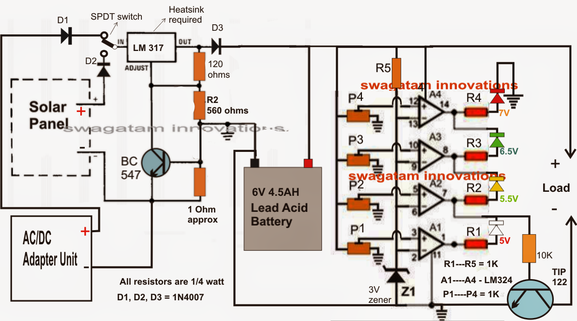
The preferred 6V solar battery charger circuit could be witnesed in the diagram in this article.

Making reference to the diagram, the different phases might be known with the aid of the following factors:

The IC LM317 which can be a regular voltage regulator IC is set up to generate a set 7V output dependent upon the resistances 120 ohms and 560 ohms.

The BC547 transistor and its base 1 ohm resistor make sure that the charging current to the 6V/4.5AH battery by no means surpasses the optimum 500mA mark.

The output of the LM317 phase is instantly associated with the 6V battery for the meant charging of the battery.

The input to this IC is selectable via a SPDT switch, either from the given solar panel or from an AC/DC adapter unit, which depends whether the solar panel is generating adequate voltage or not, which might be supervised by way of a voltmeter attached across the output pins of the LM317 IC.

The four opamps from the IC LM324 which happens to be a quad opamp in one package are cabled up as voltage comparators and deliver a visual indications for the a variety of voltage levels at any immediate, in the course of the charging method or throughout the discharging procedure by means of the associated LEd panel or another load.

All the inverting inputs of the opamps are clamped to a limited recommendation of 3V by way of the appropriate zener diode.

The non-inverting inputs of the opamps are separately connected to presets that happen to be properly set to improve with the pertinent voltage levels by producing their outputs high sequentially.

The symptoms for the identical might be checked via the linked colored LEDs.

The yellow LED connected with A2 could be set for showing the low voltage cut-off threshold. When this LED shuts off (white lights up), the transistor TIP122 is inhibited from carrying out and removes the supply to the load, therefore making certain the battery is rarely permitted to release to harmful unrecoverable boundaries.

A4 LED implies the upper full charge level of the battery....this output could possibly be fed to the base of the LM317 transistor in order to cut-off the charging voltage to the battery stopping overcharging (optional).

Please be aware that considering that the A2/A4 do not need hysteresis integrated could generate oscillations at the cut-off thresholds, which is not going to necessarily be an issue or influence the battery overall performance or life.


6.5Vsolarchargercircuit

You'll also like:

  • 1.  Automatic Solar Drip Irrigation Circuit for Home Gardens
  • 2.  Battery Current Sensor with Indicator Circuit
  • 3.  Build a Fast Seawater Desalination Plant at Home
  • 4.  How to Connect Solar Panels in Series and Parallel
  • 5.  Battery Charger for Positive Earth Cars
  • 6.  Make this Garden Solar LED Circuit

About Admin

Hey friends, Thanks a bunch for stopping by this site! I am an engineer with a Bachelor of Engineering in Electronics and Telecommunication. One of my passions is gathering information from all sorts of electronics books and tutorials. I then take that information and compile it into a language that is super easy to understand. My goal is to make those complex electronics circuit concepts and technical terms much more accessible for all the new and budding electronics engineers out there. I can also design customized circuit diagrams as required by the users.
If you have any questions related to this field, please do not hesitate to drop a comment! I am always here and ready to help you out with any queries you might have. I cannot wait to hear from you!

Reader Interactions

Leave a Reply Cancel reply

Your email address will not be published. Required fields are marked *

Primary Sidebar

Categories

  • 3 Phase (4)
  • 8051 Microcontroller (1)
  • Arduino (11)
  • Audio and Amplifier (102)
  • Automation (8)
  • Battery Chargers (64)
  • Bicycle Projects (4)
  • Car and Motorcycle Projects (39)
  • Datasheets (10)
  • DIY Projects (5)
  • Electrical (15)
  • Free Energy (6)
  • Games Projects (2)
  • High Voltage (14)
  • Hobby Projects (30)
  • Household Circuits (2)
  • IC 555 Circuits (5)
  • Ignition Circuits (2)
  • Indicators (50)
  • Infrared (6)
  • Inverter Circuits (29)
  • Lights and Lamps (97)
  • Medical (8)
  • Meter and Tester Circuits (38)
  • Motor Driver (17)
  • New Circuits (56)
  • Oscillators (30)
  • Pets and Pests (5)
  • Power supply (80)
  • Protection Circuits (25)
  • PWM (9)
  • Remote Control (20)
  • Security and Alarm Circuit (48)
  • Sensors and Detectors (66)
  • Signal Processor (23)
  • Solar Controller Circuits (62)
  • SSR (3)
  • Temperature Controller (20)
  • Timer (25)
  • Transformerless (7)
  • Transmitters (12)
  • Tutorials (45)
  • UPS (2)
  • Voltage Regulators (57)
  • Water Sensor and Controller (29)
  • Home
  • Privacy Policy
  • Contact
  • Disclaimer
  • Copyright

© 2025 · Making Easy Circuits