The following circuit makes use of an extremely common voltage boost converter idea to make a couple of white LEDs light up at fairly lower power supplies. Let's discover ways to create this fascinating and helpful little LED boost emergency light circuit.
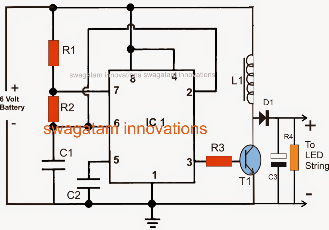
One more time we take the help of the evergreen work horse, the IC555 for applying the suggested measures. The figure demonstrates a relatively easy circuit configuration where the IC 555 continues to be rigged as an astable multivibrator.
In an astable multivibrator design the numerous parts are wired such that the output produces trains of pulses which can be self preserving and keeps arriving provided that the circuit continues to be powered.
In the present configuration the output of the IC which can be the pin #3 creates pulses at a frequency contingent on the resistors R1 and R2 as well as the capacitor C2.
R2 might be usually modified or made adjustable type for allowing dimming control of the LEDs.
In spite of this right here the value of R2 has become set for getting optimum brightness from the LEDs.
The pulses obtainable at pin#3 of the IC is utilized for ddriving the transistor T1 which often switches due to the positive pulses.
The switching of the transistor pulls the supply voltage by means of the inductor in a pulsed mode.
As we understand when changing or pulsed voltage is used across an inductor it attempts to cry out against the current and in the process kick the exact high voltage for compensating the utilized current force.
This activity of the inductor is exactly what constitutes the boost action, where the voltage is moved to higher levels than the actual supply voltage.
The above working of the inductor continues to be used in this circuit also. L1 boosts the voltage in an attempt to limit the used AC, this high voltage produced across the coil during the non carrying out stages of the transistor is fed across a series attached LEDs for lighting them under lower current levels. This method assists to irradiate the LEDs at comparatively lower power consumption.
L1 winding is not so important, it is just a few little experimenting, the number of turns, wire guage, the diameter of the core, all are instantly required and have an effect on the boost levels, therefore needs to be fully optimized very carefully.
In the prototype I had employed 50 turns of 22 SWG over a regular ferrite rod, which happens to be usually utilized in small MW radio receivers.
The LEDs utilized by me were 1 watt, 350 mA types, in spite of this you might consider using various kinds if you would like.
Parts List
R1 = 100K
R2 = 100k pot,
R3 = 100 Ohms,
R4 = 4k7, 1 watt
C1 = 680pF,
C2 = 0.01uF
C3 = 100uF/100V
L1 = see text
IC = LM555
T1 = TIP122
D1 = BA159
Make sure you Hook up A 10 OHM RESISTOR IN SERIES WITH THE LED String FOR Preserving IT FROM HIGH Stimulated VOLTAGE.
Improving THE VALUE OF R2 Ought to Boost THE Illumination OF THE LEDs AND VICE VERSA.
solar gaden night lamp circuit