• Skip to main content
  • Skip to primary sidebar

Making Easy Circuits

Learn and build electronic circuits

You are here: Home / Timer / How to Build a Aquarium Fish Feeder Timer Controller Circuit

How to Build a Aquarium Fish Feeder Timer Controller Circuit

Last Updated on February 17, 2018 by Admin 2 Comments

The submit reveals an aquarium feeder timer circuit which maintains a couple of nonstop procedures according to a fixed timing sequence by means of the particular pot controls.
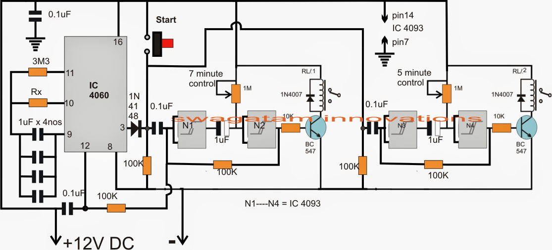
 

aquarium2Bfeeder2Btimer2Bcircuit
As demonstrated in the suggested fish feeder timer controller circuit, N1, N2 and N3, N4 are the four NAND gates from the IC 4093, set up as flip flop timer phases.
N1, N2 forms the 7 second delay timer, the period might be modified and set with the aid of the 1M pot, exactly the same N3, N4 is wired up as the second 5.2 second delay generator stage.
IC 4060 is intended as the 24 hour timer circuit for the needed cycling of the preferred time sequences.
When the circuit is operated, the 0.1uF capacitors at the inputs of N1 and N3 ground the specific inputs via the 100k resistors, providing an adverse latch across gate outputs, which often maintain transistor relay driver turned OFF.
Right now, for beginning the circuit the "start" button is pressed which reverts the gate latches to positive turning on the relays at the same time. This problem forces pin12 of IC 4060 to turn out to be high to ensure that it remains disabled for the present time.
According to the presented settings of the 1M pots, after nearly 5 minutes the capacitor at the N3 output charges up first forcing the N4 input to go high which one more time returns the latch to negative switching off the 5 second relay first, precisely similarly N2 relay follows and gets shut OFF after next 2 seconds.
The above scenario leads to the output of N2 and the input of N1 to go "low" which means that now pin12 of IC 4060 is allowed at the needed "low" which enables it to commence its counting until the mentioned 24 hour time is elapsed, when its pin3 goes high leading to an automatic activating of the above described cycle.
The method right now maintains repeating forever provided that the aquarium feeder circuit is held in the powered condition.

You'll also like:

  • 1.  Making Delay Timers using NOT gates IC 4049
  • 2.  Universal Digital, Programmable Timers Circuits
  • 3.  Dark Room Timer Circuit
  • 4.  IC 4060 based 2-step Programmable Timer Circuit
  • 5.  1 Hour to 5 Hour Customizable Timer Circuit
  • 6.  Simple Dark Room Timer Circuit for Photographers

About Admin

Hey friends, Thanks a bunch for stopping by this site! I am an engineer with a Bachelor of Engineering in Electronics and Telecommunication. One of my passions is gathering information from all sorts of electronics books and tutorials. I then take that information and compile it into a language that is super easy to understand. My goal is to make those complex electronics circuit concepts and technical terms much more accessible for all the new and budding electronics engineers out there. I can also design customized circuit diagrams as required by the users.
If you have any questions related to this field, please do not hesitate to drop a comment! I am always here and ready to help you out with any queries you might have. I cannot wait to hear from you!

Reader Interactions

Comments

  1. Sreenu says

    December 14, 2017 at 11:29 am

    Sir 4093 which pin number track connect sir pls tell me

    Reply
    • admin says

      December 15, 2017 at 8:55 pm

      Sreenu, see the following image, you will find there are 4 gates in one chip, use any of those gates anywhere within the fish feeder circuit, all gates are similar so any one can be used at any of those locations.

      how-to-understand-and-use-ic-4093-nand/

      in the fish feeder circuit the inputs pins are shorted so that makes the connections even easier

      Reply

Leave a Reply Cancel reply

Your email address will not be published. Required fields are marked *

Primary Sidebar

Categories

  • 3 Phase (4)
  • 8051 Microcontroller (1)
  • Arduino (11)
  • Audio and Amplifier (102)
  • Automation (8)
  • Battery Chargers (64)
  • Bicycle Projects (4)
  • Car and Motorcycle Projects (39)
  • Datasheets (10)
  • DIY Projects (5)
  • Electrical (15)
  • Free Energy (6)
  • Games Projects (2)
  • High Voltage (14)
  • Hobby Projects (30)
  • Household Circuits (2)
  • IC 555 Circuits (5)
  • Ignition Circuits (2)
  • Indicators (50)
  • Infrared (6)
  • Inverter Circuits (29)
  • Lights and Lamps (97)
  • Medical (8)
  • Meter and Tester Circuits (38)
  • Motor Driver (17)
  • New Circuits (56)
  • Oscillators (30)
  • Pets and Pests (5)
  • Power supply (80)
  • Protection Circuits (25)
  • PWM (9)
  • Remote Control (20)
  • Security and Alarm Circuit (48)
  • Sensors and Detectors (66)
  • Signal Processor (23)
  • Solar Controller Circuits (62)
  • SSR (3)
  • Temperature Controller (20)
  • Timer (25)
  • Transformerless (7)
  • Transmitters (12)
  • Tutorials (45)
  • UPS (2)
  • Voltage Regulators (57)
  • Water Sensor and Controller (29)
  • Home
  • Privacy Policy
  • Contact
  • Disclaimer
  • Copyright

© 2025 · Making Easy Circuits