When generating tape recordings, particularly of "live" shows, it may be quite tough to set the right recording level.
This could effortlessly result in an extreme recording level and major distortion developing except if the recording level command is retained well backed off.
The price one then needs to pay is a low recording level and following low signal to noise ratio. The standard method of eliminating this issue is to try using an audio limiter circuit ahead of the tape deck.
This unit usually moves the signal directly via towards the recorder, however, if the input surpasses a preset threshold level it attenuates the signal so the output level is just not adequate to overload the recorder.
With audio limiter circuit the input signal is placed on an attenuator which can be created through R1 and PCC1.
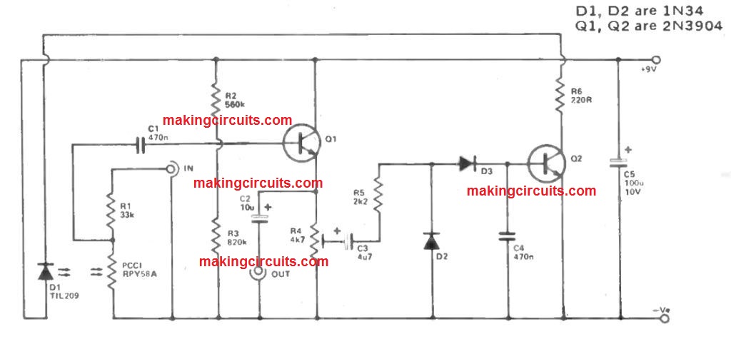
Usually PCC1 is within complete darkness and displays a really high resistance (generally a few megohms) leading to marginal failures with the attenuator.
This kind of stage feeds into the high input impedance of the emitter follower buffer stage created through Q1 as well as its connected elements, which guarantees minor loss of signal level.
Hence the input signal is generally fed directly via towards the output socket along with just a minor loss of amplitude.
A few of the output signal is fed through the slider of R4 to a rectifier and smoothing circuit which can be composed of D2, D3, and C4.
If the input signal is adequately powerful, the positive bias created by the audio limiter circuit will probably be sufficient to switch on Q2 and light generating diode D1 which can be linked in its collector circuit.
The light output through D1 is directed at the sensitive surface of PCC1 (the surface to which the leadout wires do not link) which leads to a big decrease in the resistance of PCC1.
This provides the specified attenuation of the signal. The bigger the input signal is created, the greater firmly D1 glows, plus the higher the reduction in circuit gain.
This technique has got the a result of avoiding the output level through increasing far over a level from which D1 starts to at first turn on.
Within the prototype this threshold level reaches around 230 mV (along with R4's slider at the top of its track) and raising the input level to 4 volts RMS triggers the output to increase to only around 320 mV.
Greater threshold levels can be acquired along with R4's slider modified down its track to the suitable point.
The attack and decay times of the circuit both are pretty limited in order that the unit rapidly reacts to changes in signal level and is not generally noticeable in functioning.
Building of the unit needs to be pretty simple, however the unit should obviously be stored in a light proof box to ensure that PCC1 is protected from the ambient illumination.
D1 and PCC1 are installed as near jointly as you can. The current utilization of the audio limiter circuit is just around 1 to 5 mA based on the input level.
I am considering the Audio Limiter Circuit. I cannot find sources for the BA741 and BFW11. Where did you get yours?
Alan P.
Just a minor but critical mistake in the circuit diagram…
The diagram shows this point as not connected but voltage divider R2 & R3 junction should be connected to the base of Q1 for biasing the transistor.
Yep, you are absolutely right….I hope the other readers will understand this mistake and do the needful.
I am trying to build a dynamic mic compressor circuit but am having a tough time doing this. I don’t want any noticeable audio colorization of the mic’s sound and to operate it from a 9 volt battery. Just one level pot. Male XLR to female XLR jacks. I have tried fets, opto-couplers, diodes only,etc. Of course the output from a dynamic mic is too low to be clamped from just about any type of diode used. Thank you for any help that you can give.
I will surely try to help with a suitable circuit soon…