• Skip to main content
  • Skip to primary sidebar

Making Easy Circuits

Learn and build electronic circuits

You are here: Home / New Circuits / Automatic Central Heating Controller Circuit

Automatic Central Heating Controller Circuit

Last Updated on June 26, 2020 by Admin Leave a Comment

Manually controlling the boiler thermostat of your central heating system according to the season will require the boiler to be turned on and off too many times, especially during the winter days, as indicated in the following graph.

cold weather
swith ON temp

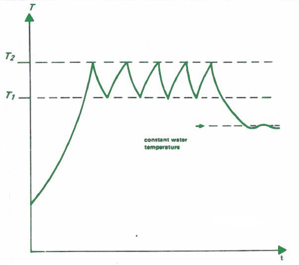
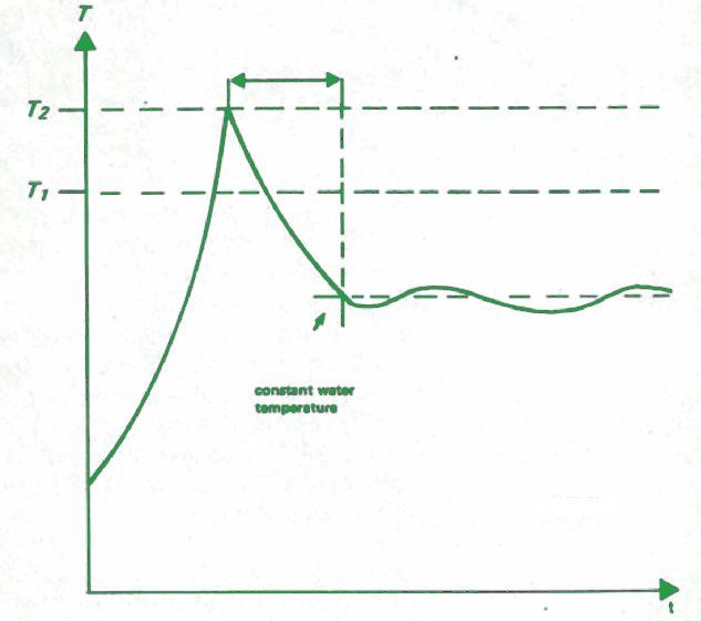
The solution for this is the circuit explained below that prevents the switching on of the boiler for a certain period td after the threshold temperature for switch-off, T2 has been attained.

The boiler temperature T would have fallen far below the critical temperature for switch-on, T1 by the time td has passed.

How the Circuit Works

Referring to the circuit diagram below the result is obtained by extending that of the central heating monitor, connecting the make contacts of a relay into the boiler circuit of 24 V.

ch controller

Depending on the state of the N2-N3 bistable, the transistor T1 will be on or off, or in other words, the 24 V circuit will be open or closed. T1 starts conducting, td starts and the IC2 reset is cancelled from the moment the bistable gets set.

When IC2 reaches maximum value after a period, the logic level selected by S1 at the output changes and this resets the bistable through N4. This marks the end of td.

N1, R3-C2 and R2-C1 connect the set input of the bistable to the collector of T3 in the central heating monitor circuit. This transistor controls the LED that acts as the indicator for the interrupted heat request for the thermostat.

The time range for td is wide and can be controlled using P1 and S1. A value of 10 minutes for td restricts the turning on and off of the boiler to 6 times in an hour.

How to Set up the Central Heating Controller

You can, of course, change td by changing P1 and S1 by noting how many times the LEDs in the central heating system for this lights up. You must set the bistable by connecting the R3-C2 junction to earth for a moment to extinguish D3 and start td.

Then change P1 to set the time after which D3 lights to 5, 10 or 20 minutes. Other possibilities are 4, 8 or 16 and 6, 12 or 24 minutes.

You'll also like:

  • 1.  How to Build a Automatic PIR Controlled Fan Circuit for Schools and Colleges
  • 2.  Electronic Dice Circuit
  • 3.  Easy FET Circuits you can Build and Use
  • 4.  Dry Run Protection for Motor using Reed Relay Switch
  • 5.  0 – 30 V Regulated Power Supply Circuit
  • 6.  Simple Peltier Refrigerator Circuit

About Admin

Hey friends, Thanks a bunch for stopping by this site! I am an engineer with a Bachelor of Engineering in Electronics and Telecommunication. One of my passions is gathering information from all sorts of electronics books and tutorials. I then take that information and compile it into a language that is super easy to understand. My goal is to make those complex electronics circuit concepts and technical terms much more accessible for all the new and budding electronics engineers out there. I can also design customized circuit diagrams as required by the users.
If you have any questions related to this field, please do not hesitate to drop a comment! I am always here and ready to help you out with any queries you might have. I cannot wait to hear from you!

Reader Interactions

Leave a Reply Cancel reply

Your email address will not be published. Required fields are marked *

Primary Sidebar

Categories

  • 3 Phase (4)
  • 8051 Microcontroller (1)
  • Arduino (11)
  • Audio and Amplifier (102)
  • Automation (8)
  • Battery Chargers (64)
  • Bicycle Projects (4)
  • Car and Motorcycle Projects (39)
  • Datasheets (10)
  • DIY Projects (5)
  • Electrical (15)
  • Free Energy (6)
  • Games Projects (2)
  • High Voltage (14)
  • Hobby Projects (30)
  • Household Circuits (2)
  • IC 555 Circuits (4)
  • Ignition Circuits (2)
  • Indicators (50)
  • Infrared (6)
  • Inverter Circuits (29)
  • Lights and Lamps (97)
  • Medical (8)
  • Meter and Tester Circuits (38)
  • Motor Driver (17)
  • New Circuits (56)
  • Oscillators (30)
  • Pets and Pests (5)
  • Power supply (81)
  • Protection Circuits (25)
  • PWM (8)
  • Remote Control (20)
  • Security and Alarm Circuit (48)
  • Sensors and Detectors (66)
  • Signal Processor (23)
  • Solar Controller Circuits (61)
  • SSR (3)
  • Temperature Controller (20)
  • Timer (25)
  • Transformerless (7)
  • Transmitters (12)
  • Tutorials (45)
  • UPS (2)
  • Voltage Regulators (57)
  • Water Sensor and Controller (29)
  • Home
  • Privacy Policy
  • Contact
  • Disclaimer
  • Copyright

© 2025 · Making Easy Circuits