• Skip to main content
  • Skip to primary sidebar

Making Easy Circuits

Learn and build electronic circuits

You are here: Home / Indicators / Automatic LDR Switch Circuit with Flashing Lamp

Automatic LDR Switch Circuit with Flashing Lamp

Last Updated on November 27, 2024 by Admin Leave a Comment

This simple flashing LED light will begin flashing as soon as darkness sets in, and will shut off in the morning when day light arrives back.

The operation of the LDR switch is to automatically turn the flashing lights on when its dark and off again with there is natural light availble. This feature makes it ideal for its use as as a warning light when facing obstructions.

One more use of this flashing twilight switch would be in the field of education to signify the operation of transistors in conjunction with opto-electronics.

How the Circuit Works

The transistor conducts sufficient base current through T1 as the LDR (Light Dependent Resistor) has a low resistance value during daytime. The L1 Lamp then stays off as the collector voltage is small and the n-p-n darlington, T2 is off as well.

twilight switch

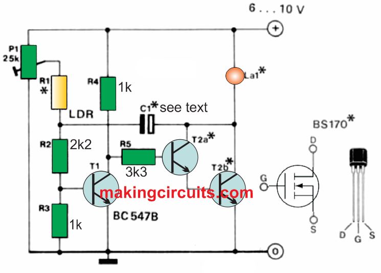
With the ambient light intensity decreases significantly, there is an increase in the resistance of the LDR.

The collector voltage then increases as the base current in T1 becomes insufficient and it switches off which in turn makes T2 conduct electricity and you find Lamp L1 is illuminated.

The fall in the collector voltage of T2 to nearly 0V makes the potential immediately applicable to the base T1 using capacitor C1 which helps cut off T1. The LDR is then illuminated by the lighted lamp L1 as the capacitor is charged via P1.

The LDR diminishes in accordance to the optical feedback which makes the voltage across R2 increase which in turn makes T1 conduct again. A new cycle is started as the darlington is switched off and the lamp goes out.

The value of C1 (47uF) is responsible for regulating the flashing frequency This low value increases the frequency by reducing the capacitance.

LED lamp Specification

The other alternatives to the BC 517 darlington are Two numbers of BC 547B transistors or a small signal MOSFET. The observational point is the current through lamp L1. Maximum permissible current through the lamp through 2 nos of BC 547Bs is 100mA, BC 517 is 400mA and with a suitable MOSFET it is 500mA.

When the lamp L1 is off, the current consumption by the circuit is about 8mA at 6V and 10mA at 10V.

A commonly available type of LDR is used, namely, LDR 03, 05, 07.

For best results, the LDR must be fitted near lamp L1. Onset of operation is set with P1.

You'll also like:

  • 1.  How to Make a 4 LED Temperature Indicator Circuit
  • 2.  Simple Crystal Tester Circuit
  • 3.  LED Voltage Monitor Circuit
  • 4.  Doorbell With Memory Circuit
  • 5.  Simple Door Security Alarm Circuit
  • 6.  Transistorized Music Level Indicator Circuits for Amplifiers

About Admin

Hey friends, Thanks a bunch for stopping by this site! I am an engineer with a Bachelor of Engineering in Electronics and Telecommunication. One of my passions is gathering information from all sorts of electronics books and tutorials. I then take that information and compile it into a language that is super easy to understand. My goal is to make those complex electronics circuit concepts and technical terms much more accessible for all the new and budding electronics engineers out there. I can also design customized circuit diagrams as required by the users.
If you have any questions related to this field, please do not hesitate to drop a comment! I am always here and ready to help you out with any queries you might have. I cannot wait to hear from you!

Reader Interactions

Leave a Reply Cancel reply

Your email address will not be published. Required fields are marked *

Primary Sidebar

Categories

  • 3 Phase (4)
  • 8051 Microcontroller (1)
  • Arduino (11)
  • Audio and Amplifier (102)
  • Automation (8)
  • Battery Chargers (64)
  • Bicycle Projects (4)
  • Car and Motorcycle Projects (39)
  • Datasheets (10)
  • DIY Projects (5)
  • Electrical (15)
  • Free Energy (6)
  • Games Projects (2)
  • High Voltage (14)
  • Hobby Projects (30)
  • Household Circuits (2)
  • IC 555 Circuits (5)
  • Ignition Circuits (2)
  • Indicators (50)
  • Infrared (6)
  • Inverter Circuits (29)
  • Lights and Lamps (97)
  • Medical (8)
  • Meter and Tester Circuits (38)
  • Motor Driver (17)
  • New Circuits (56)
  • Oscillators (30)
  • Pets and Pests (5)
  • Power supply (80)
  • Protection Circuits (25)
  • PWM (9)
  • Remote Control (20)
  • Security and Alarm Circuit (48)
  • Sensors and Detectors (66)
  • Signal Processor (23)
  • Solar Controller Circuits (62)
  • SSR (3)
  • Temperature Controller (20)
  • Timer (25)
  • Transformerless (7)
  • Transmitters (12)
  • Tutorials (45)
  • UPS (2)
  • Voltage Regulators (57)
  • Water Sensor and Controller (29)
  • Home
  • Privacy Policy
  • Contact
  • Disclaimer
  • Copyright

© 2025 · Making Easy Circuits