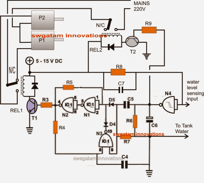
The article describes a basic circuit for a water level controller that may be used to automatically turn on and off two submersible water pumps depending on to a preset water level switch. Just one integrated circuit and some more passive components make up the whole circuit. One of the blog's enthusiasts submitted the proposal.
Technical Details
Could you please assist me with this issue? A couple of submersible pumps and float switches (P1 and P2) fitted in a basement sump provide a certain amount of redundancy.
Every time a predetermined water level is achieved, we are interested in switching between P1 and P2 to use the two pumps evenly. In other words, P1 must commence and pump the water out as soon as the preset level is achieved. The subsequent attempt, P2 must begin and pump the water out when the predetermined level is achieved.
subsequently will be P1's turn the following time, and and so on. An "alternating" relay control that operates P1 and P2 sequentially is what we require.
The layout
An automated submersible pump controller's circuit may be interpreted as follows:
As is evident, a single IC 4093 serves as the foundation for the complete circuit, which consists of four NAND gates.
A typical flip flop circuit is formed by the gates N1–N3, where each positive trigger at the junction of C5/R6 causes the output of N2 to toggle from high to low and the other way around.
To detect an existence of water across a preset fixed level within the tank, N4 is set up as a buffer and its input finishes as the sensing input.
We have a circuit with a connection from the ground or negative terminal placed in the tank water near the sensing input of N4 above it.
Initial State Without Water
In the first scenario when there is no water in the tank N4 stays high because of R8. This results in a low output at the junction of C5 and R6.
As a result N1 N2 and N3 remain inactive keeping T1 and T2 OFF. This means that relays REL1 and REL2 are also off with their contacts in a normally closed (N/C) position. During this time REL2 ensures that the supply voltage is disconnected from the motors since there is no water.
Water Rising in the Tank
Now when the water level rises it connects the ground to N4 causing N4 to drop to a low state. This change leads to a high output from N4.
The high output activates T2 and REL2 and it also flips the output of N2 which activates REL1. At this point REL2 allows mains voltage to flow to the motors. With REL1 engaged it activates pump P2 through its normally open (N/O) contacts.
Water Level Drops
Once the water level falls below a set threshold N4 goes back to a low output again. However this low signal does not affect REL1 because N1 N2 and N3 keep REL1 activated.
On the other hand REL2 switches OFF due to the low output from N4 cutting off mains supply to the motors and deactivating P2.
Alternating Pump Operation
In the next cycle when the water level rises again to the sensing points N4 toggles REL2 back on allowing mains supply to reach the motors again. REL1 also switches but changes to its N/C contact.
This action activates pump P1 since P1 is connected to the N/C of REL1. As a result P2 turns OFF while P1 starts operating.
Continuous Cycle
This alternating activation of P1 and P2 keeps repeating as per the described operations with each cycle of water level changes.
Circuit Diagram

Parts list for the above automatic submersible pump controller circuit:
| Component | Value |
|---|---|
| R3, R9 | 10K |
| R4, R5, R8 | 2M2 |
| R6, R7 | 39K |
| R4, R5 | 0.22, DISC |
| C6 | 100µF/25V |
| D4, D5 | 1N4148 |
| C4, C5, C7 | 0.22µF |
| T1, T2 | BC 547 |
| N1---N4 | IC4093 |
| Relays | 12V, SPDT, 20 amp contacts |
| Diodes | 1N4007 |
Leave a Reply