The post below explains how to convert a whistling sound into an enhanced musical output through an electronic circuit.
Music soothes our soul and make us feel good. We like to play any of the musical instruments in our free time. But we have lack of time for these activities. The Easy music circuit helps us in making our own music, we just need to whistle in tune.
Block Diagram
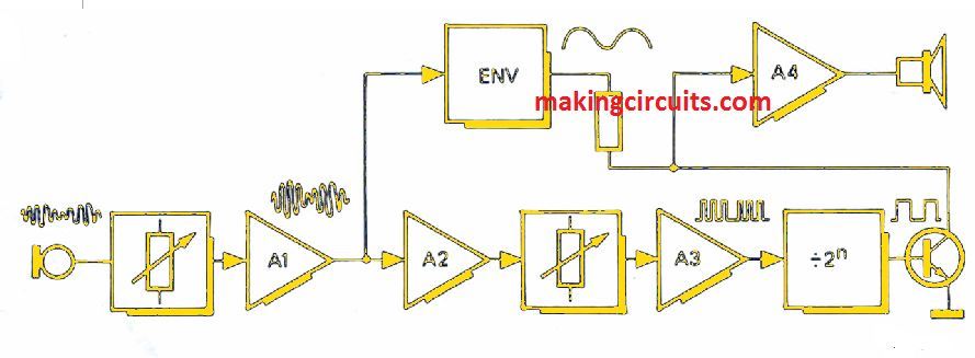
A block diagram is shown and it can be seen that the principle of 'Easy music' is simple. An op-amp A1 amplifies the musician whistle picked by the crystal microphone.
An envelope follower is fed up a portion of signal. Signal is rectified and filtered to produce a positive voltage. The positive voltage thus produced follows the input signal amplitude envelope.
The signal is now fed to the two limiting amplifiers. At same frequency, variable amplitude sine wave is converted to constant amplitude square wave.
The square wave produced is used to clock a binary counter. The output of binary counter should be 1,2,3...octaves below input signal so a division ratio is set to 2,4,8 etc.
Counter output is used for switching transistor T1 on and off. The output amplifier A4 is fed by the T1 collector signal.
Envelope follower output supplies voltage to T1 collector receiver. Hence, the collector signal amplitude and the output signal varies with amplitude of input signal.
Thus, a square wave output is produced having frequency one or more octaves below the input signal. But, its amplitude dynamics is similar to the amplitude of input signal.
How the Circuit Works
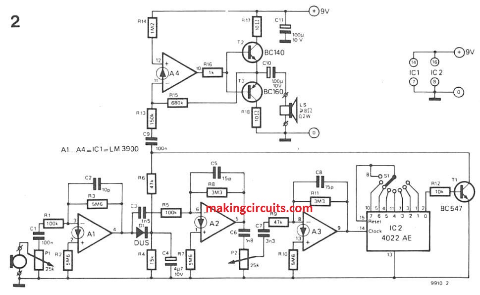
The circuit is shown in figure above and the sections can be easily viewed. P1 functions as a sensitivity control which is fed by the output of a crystal microphone.
A1 having a gain value of 56 is connected as a linear amplifier. C4 is used to store the resulting peak voltage which is produced by rectification of a part of the output signal. A2 and A3 again amplifies the A1 output signal.
To cause limiting at A3 output combined gain of A1 to A3 is sufficient. The limiting is done with the smallest input signals that are adjusted by P2.
P2 is mainly responsible for adjusting the gain of the limiting amplifier. It is done so that limiting can be done with smallest input signals thus avoiding limiting caused by noises.
S1 is used for the division of CMOS counter. A3 output is used for clocking of the CMOS binary counter. IC2 is responsible for on and off switching of transistor.
Amplitude of collector signal varies according to input signal because C4 supplies voltage to the collector resistor (R6) of T1. At last, the signal is amplified by an audio power amplifier which is being built around A4. It also drives a small loudspeaker.
Applications
Just like several other things applications are infinite in this easy music system too. To increase the tonal possibilities of the instrument filters and other circuits can also be added.
Addition of these circuits produce different output waveforms. The reader is suggested to do some research if willing to know more about easy music system.
Leave a Reply