• Skip to main content
  • Skip to primary sidebar

Making Easy Circuits

Learn and build electronic circuits

You are here: Home / Ignition Circuits / Diesel Engine Delay Start Circuit

Diesel Engine Delay Start Circuit

Last Updated on January 10, 2018 by Admin 2 Comments

In this post we make a simple delay start circuit for diesel engines in order to enable a proper preheat

It happens to be well known that diesel engines need a preheating delay time of approximately 5 seconds. When we attempt to start the engine with the cold diesel it is not going to not start regardless of how rigorously we try. The truth is this adversely tends to make an engine of this type to start before warming up. The circuit we recommend will take around seven seconds before enabling us to start the engine.

Diesel Engine Delay Start Circuit

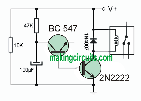
The resistance of 47K and the capacitor of 100μF along with the transistor of the center are the ones that are responsible for recognizing the timing. The second transistor is liable for moving the coil of the relay as well as the latter is in charge of making it possible for the engine to start.

For this simple diesel engine delay start circuit we put together almost all the equipment inside a relay box very easily or in a suitable small molded case. For longer time delay we simply may tweak on the values ​​of capacitor and resistance. The circuit is operated straight by 12V.

You'll also like:

  • 1.  How to Build a Button Start Ignition Circuit

About Admin

Hey friends, Thanks a bunch for stopping by this site! I am an engineer with a Bachelor of Engineering in Electronics and Telecommunication. One of my passions is gathering information from all sorts of electronics books and tutorials. I then take that information and compile it into a language that is super easy to understand. My goal is to make those complex electronics circuit concepts and technical terms much more accessible for all the new and budding electronics engineers out there. I can also design customized circuit diagrams as required by the users.
If you have any questions related to this field, please do not hesitate to drop a comment! I am always here and ready to help you out with any queries you might have. I cannot wait to hear from you!

Reader Interactions

Comments

  1. Luciano Martínez says

    August 6, 2022 at 10:47 pm

    Dónde va conectado el emisor del BC547 para que funcione ?

    Reply
    • admin says

      August 11, 2022 at 10:34 pm

      The bc547 works like a diode, the emitter is intentionally left unconnected.

      Reply

Leave a Reply Cancel reply

Your email address will not be published. Required fields are marked *

Primary Sidebar

Categories

  • 3 Phase (4)
  • 8051 Microcontroller (1)
  • Arduino (11)
  • Audio and Amplifier (102)
  • Automation (8)
  • Battery Chargers (64)
  • Bicycle Projects (4)
  • Car and Motorcycle Projects (39)
  • Datasheets (10)
  • DIY Projects (5)
  • Electrical (15)
  • Free Energy (6)
  • Games Projects (2)
  • High Voltage (14)
  • Hobby Projects (30)
  • Household Circuits (2)
  • IC 555 Circuits (5)
  • Ignition Circuits (2)
  • Indicators (50)
  • Infrared (6)
  • Inverter Circuits (29)
  • Lights and Lamps (97)
  • Medical (8)
  • Meter and Tester Circuits (38)
  • Motor Driver (17)
  • New Circuits (56)
  • Oscillators (30)
  • Pets and Pests (5)
  • Power supply (80)
  • Protection Circuits (25)
  • PWM (9)
  • Remote Control (20)
  • Security and Alarm Circuit (48)
  • Sensors and Detectors (66)
  • Signal Processor (23)
  • Solar Controller Circuits (62)
  • SSR (3)
  • Temperature Controller (20)
  • Timer (25)
  • Transformerless (7)
  • Transmitters (12)
  • Tutorials (45)
  • UPS (2)
  • Voltage Regulators (57)
  • Water Sensor and Controller (29)
  • Home
  • Privacy Policy
  • Contact
  • Disclaimer
  • Copyright

© 2025 · Making Easy Circuits