• Skip to main content
  • Skip to primary sidebar

Making Easy Circuits

Learn and build electronic circuits

You are here: Home / Audio and Amplifier / Dynamic MIC Preamplifier Circuit

Dynamic MIC Preamplifier Circuit

Last Updated on November 16, 2024 by Admin 3 Comments

In this post we discuss a powerful preamplifier circuit for microphones, which can be used for amplifying an electret MIC signal, using just a couple of BJTs.

Microphone signals will often be too weak to get carried to units for example mixing consoles and recording devices with sufficient strength. Preamplifiers boost a microphone signal to line level (i.e. the amount of signal power necessary by this kind of equipment) by giving steady gain and also protecting against induced disturbance that could in any other case distort the signal.
The output voltage for a dynamic microphone is quite low, usually in the 1 to 100 microvolt range. A microphone preamplifier raises this amount by up to 70 dB, to just about anywhere up to 10 volts. This more powerful signal can be used to operate equalization circuitry inside an audio mixer, to push external sound results, and also to sum for some other signals to produce an audio mix for audio recording or for live audio.

MIC preamplifier circuit dynamic

Circuit Description

By using just a couple of BC547 NPNs or Equivalent, and through a directly coupled circuit we can make a MIC preamplifier circuit for amplifying minute mic signals into very strong signal.

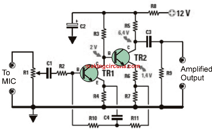
Figure 2: Electrical diagram (the voltages indicated have
Were measured by supplying the circuit with a voltage of 12 V).

TECHNICAL CHARACTERISTICS of this MIC preamp :
Required Supply voltage 9 to 18 V
Current consumption at 12 V 1.5 mA
Minimum input signal 30 mVpp
Maximum Output Signal at 12 V 7.5 Vpp
Bandwidth 10 Hz to 40 KHz
Average gain 250


Bill of Materials
R1 =100 k preset
R2 =47 k
R3 =82 k
R4 =560
R5 =4.7 k
R6 =680Ω
R7 =680Ω
R8 =100Ω
R9 =47 k
R10 =100 k
R11 ... 100 k
C1 =390 nF polyester
C2 =10 μF electrolytic
C3 =1 μF polyester
C4 =1 μF polyester
TR1 =BC547
TR2 =BC547

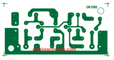
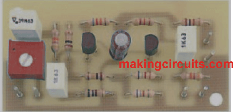
PCB Design and Component layout

pcb 3 proto

You'll also like:

  • 1.  Realistic Machine Gun Sound Effect Generator Circuit
  • 2.  DIY Guitar Jammer Circuit: Mix Tracks and Play Like a Pro
  • 3.  Designing a MOSFET Power Amplifier Circuit
  • 4.  Simple 300 Watt Power Amplifier Circuit using Transistors
  • 5.  Door Buzzer Circuit
  • 6.  Simple Telephone Amplifier Circuit

About Admin

Hey friends, Thanks a bunch for stopping by this site! I am an engineer with a Bachelor of Engineering in Electronics and Telecommunication. One of my passions is gathering information from all sorts of electronics books and tutorials. I then take that information and compile it into a language that is super easy to understand. My goal is to make those complex electronics circuit concepts and technical terms much more accessible for all the new and budding electronics engineers out there. I can also design customized circuit diagrams as required by the users.
If you have any questions related to this field, please do not hesitate to drop a comment! I am always here and ready to help you out with any queries you might have. I cannot wait to hear from you!

Reader Interactions

Comments

  1. Dimitri says

    January 20, 2023 at 9:06 pm

    The performance / simplicity ratio is absolutely amazing! It’s almost linear from 20Hz up to 60kHz. Very low distortion. Thanks for the schematic and for the testpoints voltages.

    Reply
    • admin says

      January 26, 2023 at 2:17 pm

      Thank you, and glad you found the post useful.

      Reply
  2. Hps nagi says

    December 9, 2022 at 12:55 pm

    nice. showing voltage across bc547 .6.4 2.1.4 of output.also show voltage of input across transistor

    Reply

Leave a Reply Cancel reply

Your email address will not be published. Required fields are marked *

Primary Sidebar

Categories

  • 3 Phase (4)
  • 8051 Microcontroller (1)
  • Arduino (11)
  • Audio and Amplifier (102)
  • Automation (8)
  • Battery Chargers (64)
  • Bicycle Projects (4)
  • Car and Motorcycle Projects (39)
  • Datasheets (10)
  • DIY Projects (5)
  • Electrical (15)
  • Free Energy (6)
  • Games Projects (2)
  • High Voltage (14)
  • Hobby Projects (30)
  • Household Circuits (2)
  • IC 555 Circuits (5)
  • Ignition Circuits (2)
  • Indicators (50)
  • Infrared (6)
  • Inverter Circuits (29)
  • Lights and Lamps (97)
  • Medical (8)
  • Meter and Tester Circuits (38)
  • Motor Driver (17)
  • New Circuits (56)
  • Oscillators (30)
  • Pets and Pests (5)
  • Power supply (80)
  • Protection Circuits (25)
  • PWM (9)
  • Remote Control (20)
  • Security and Alarm Circuit (48)
  • Sensors and Detectors (66)
  • Signal Processor (23)
  • Solar Controller Circuits (62)
  • SSR (3)
  • Temperature Controller (20)
  • Timer (25)
  • Transformerless (7)
  • Transmitters (12)
  • Tutorials (45)
  • UPS (2)
  • Voltage Regulators (57)
  • Water Sensor and Controller (29)
  • Home
  • Privacy Policy
  • Contact
  • Disclaimer
  • Copyright

© 2025 · Making Easy Circuits