The post details the construction of a high power lead acid battery charger circuit which will charge the connected battery at a reasonably fast rate.
Although lead-acid batteries are not as popular in electronics as NiCd ones, there is still use for them and so, there is a demand for chargers for them too. The circuit described here can charge 6 V and 12 V lead acid batteries rapidly.
It also has the mechanism for automatic switch-off on completion of charge and protective measures against short circuits, thermal overload and battery polarity reversal.
Modern sealed lead-acid batteries are quite useful in that you can even use them upside down. For each cell, use 2.3 V for normal charging and 2.45 V for fast charging. Thus a 6 V battery requires 6.9 V charging voltage while a 12 V battery requires 13.8 V.
For fast charging of a lead acid battery using this circuit, the charging current does not need to be within the 0.1-1 C range (=capacity in Ah, actual figure differs with manufacturer). Instead when the charging current falls to 1% of its capacity, the battery can be assumed to be fully charged.
A few manufacturers will advise you to charge the lead-acid battery you buy from them horizontally. Also bear in mind that you must never use an NiCd battery charger to charge a PbH2SO4 battery.
How the Circuit Works
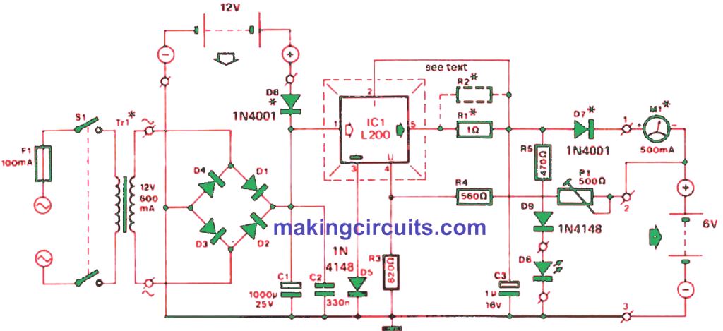
The simple lead acid charger circuit described here is built on an IC L200 voltage regulator to maintain a level charging voltage.
When there is no battery, the voltage is fixed using P1. R1 and R2 resistors are used to limit the current, R2 being needed only for a charging current over 0.5 A or to allow a more precise output current.
The current stays within [ 0.45 (R1 + R2) / R1R2 ] A, the value being shown by M1.
You may choose to install the L200 on a small heat sink although it is not mandatory due to the intrinsic thermal protection of the device. The charger is powered by the mains, but a 12 V car battery is also an option.
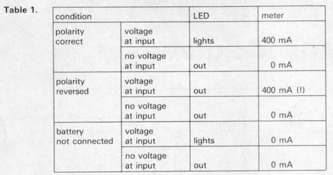
Some likely unwanted scenarios are listed in Table 1. The table, however, does not apply in the case of the battery being flat. The battery must then be checked for correct connections to the charger terminals. The LED indicator will also fail to function properly in the beginning.
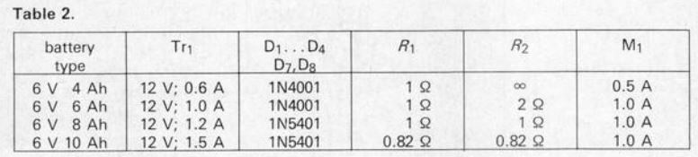
Table 2 shows the circuit variations for the different types of 6 V batteries. The charging current is kept within 1/10 of the battery capacity measured in Ah, which is safe in all cases.
For Charging 12 V Battery
When used to charge 12 V batteries, the mains transformer should have at least 18 V for the secondary voltage, C1 must be of 35 V type, R1 must be raised to 1k8 and P1 must be replaced with a 1 kΩ preset.
Complete PCB Design

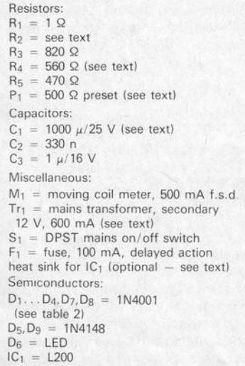
Part List
Leave a Reply