• Skip to main content
  • Skip to primary sidebar

Making Easy Circuits

Learn and build electronic circuits

You are here: Home / Power supply / High Current LM317 Power Supply Circuit

High Current LM317 Power Supply Circuit

Last Updated on January 10, 2018 by Admin 1 Comment

The high current LM317 power supply circuit shown down the page makes use of an supplemental winding or possibly a independent transformer to deliver power to the LM317 regulator in order that the outboard pass transistors are able to work nearer to saturation and strengthen efficiency.

To get decent efficiency the voltage with the collectors of the a pair of parallel 2N3055 pass transistors needs to be near to the output voltage.

The LM317 takes a few added volts on the input side, as well the emitter/base drop from the 3055s, and also no matter what is shed along the (0.1 ohm) equalling resistors (1volt at 10 amps), therefore a different transformer and rectifier/filter circuit is employed which adds some volts more than the output voltage.

The LM317 will supply more than 1 amp of current to push the bases of the external power transistors and with an approximate gain of TEN the combo ought to provide 15 amps or even more.

The LM317 constantly works using a voltage variation of 1.2 between the output and adjustment terminals and demands a minimal load of 10mA, hence a 75 ohm resistor has been picked that will probably bring (1.2/75 = 16mA).

This exact same current runs via the emitter resistor of the 2N3904 which will create around a 1 volt drop over the 62 ohm resistor as well as 1.7 volts on the base.

The output voltage is scheduled using the voltage divider (1K/560) to ensure that 1.7 volts can be ascribed to the 3904 base once the output is 5 volts.

With regard to 13 volt procedure, the 1K resistor could possibly be altered to approximately 3.6K. The regulator is without output short-circuit protection therefore the output most likely must include a correctly rated fuse.
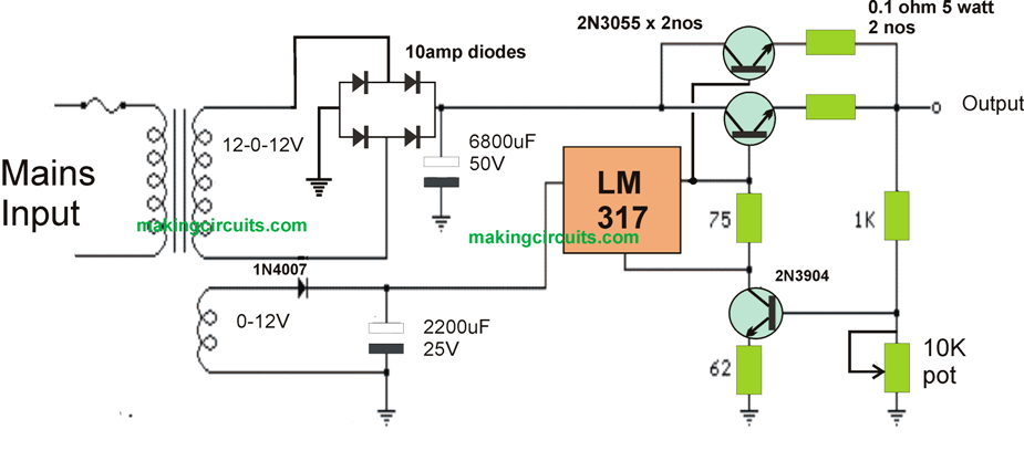
high current LM317 power supply circuit

You'll also like:

  • 1.  Simple 0.6V to 12V Boost Converter Circuit
  • 2.  How to Calculate Ferrite Transformer for SMPS
  • 3.  Simple Transformerless Power Supply Circuit
  • 4.  24V to 12V DC Buck Converter Circuit
  • 5.  Constant Current Adapter Circuit
  • 6.  High End Bench Power Supply with Variable Voltage/Current

About Admin

Hey friends, Thanks a bunch for stopping by this site! I am an engineer with a Bachelor of Engineering in Electronics and Telecommunication. One of my passions is gathering information from all sorts of electronics books and tutorials. I then take that information and compile it into a language that is super easy to understand. My goal is to make those complex electronics circuit concepts and technical terms much more accessible for all the new and budding electronics engineers out there. I can also design customized circuit diagrams as required by the users.
If you have any questions related to this field, please do not hesitate to drop a comment! I am always here and ready to help you out with any queries you might have. I cannot wait to hear from you!

Reader Interactions

Comments

  1. Rod says

    September 16, 2019 at 1:40 pm

    Why does the secondary output of the transformer feeding the bridge rectifier labeled as 12-0-12V? This suggest a center tap but not shown and would not be suitable for a bridge rectifier. Of course, a 12-0-12V would give an output of 24V if configured the way it’s presented. Some novice may think that you actually need a transformer with 12-0-12V secondary output to build the circuit. Otherwise, it’s a nice voltage regulator circuit design.

    Reply

Leave a Reply Cancel reply

Your email address will not be published. Required fields are marked *

Primary Sidebar

Categories

  • 3 Phase (4)
  • 8051 Microcontroller (1)
  • Arduino (11)
  • Audio and Amplifier (102)
  • Automation (8)
  • Battery Chargers (64)
  • Bicycle Projects (4)
  • Car and Motorcycle Projects (39)
  • Datasheets (10)
  • DIY Projects (5)
  • Electrical (15)
  • Free Energy (6)
  • Games Projects (2)
  • High Voltage (14)
  • Hobby Projects (30)
  • Household Circuits (2)
  • IC 555 Circuits (5)
  • Ignition Circuits (2)
  • Indicators (50)
  • Infrared (6)
  • Inverter Circuits (29)
  • Lights and Lamps (97)
  • Medical (8)
  • Meter and Tester Circuits (38)
  • Motor Driver (17)
  • New Circuits (56)
  • Oscillators (30)
  • Pets and Pests (5)
  • Power supply (80)
  • Protection Circuits (25)
  • PWM (9)
  • Remote Control (20)
  • Security and Alarm Circuit (48)
  • Sensors and Detectors (66)
  • Signal Processor (23)
  • Solar Controller Circuits (62)
  • SSR (3)
  • Temperature Controller (20)
  • Timer (25)
  • Transformerless (7)
  • Transmitters (12)
  • Tutorials (45)
  • UPS (2)
  • Voltage Regulators (57)
  • Water Sensor and Controller (29)
  • Home
  • Privacy Policy
  • Contact
  • Disclaimer
  • Copyright

© 2025 · Making Easy Circuits