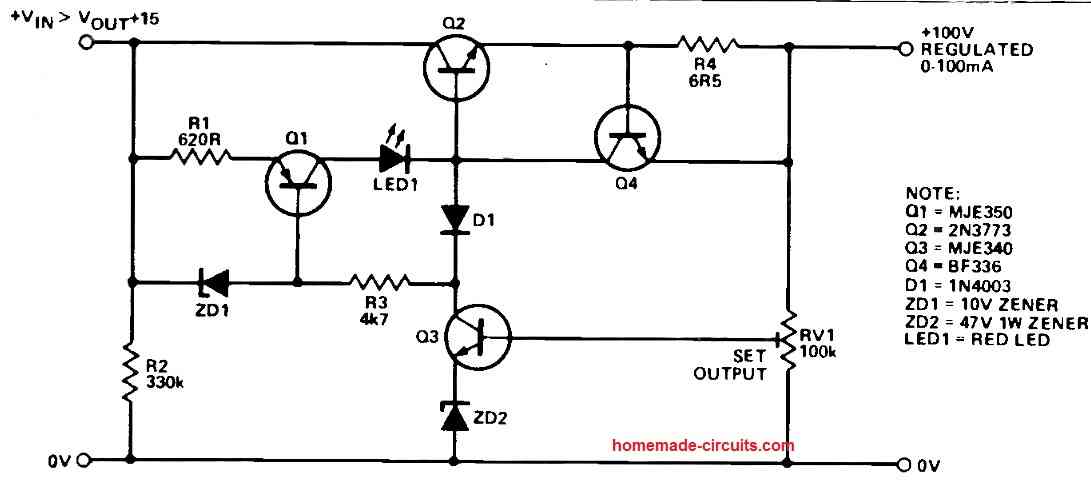
When working with electrical circuits, a well-regulated power supply is crucial. In addition to providing a controlled high output voltage that ranges from 50V to 100V, the design we propose here incorporates overcurrent limit feature to avert potential hazards. Let's investigate the intricacies of this power supply circuit, learning about its unique features and operation.
Circuit Diagram

High Output Voltage Range and Current Limit
This power supply design's ability to provide an output voltage between 50 and 100 volts is what makes it so crucial to have.
Its inherent current limiting function, which is thankfully, is what really sets it apart.
An regulated power supply to the attached load is ensured by the output current's effective limitation of 100mA.
It is possible to adapt to increased current needs with minor adjustments.
Short Circuit Protection
This design's proactive protection system is one of its fascinating features.
The power supply system intervenes if there is a short circuit or an abnormally low load resistance that causes the output voltage to drop beyond the set value.
It immediately cuts off to avoid any possible risks or damage.
This protection makes sure that even under difficult situations, your circuits and components stay safe.
Using a Transistor to Limit Current
Transistor Q4 is a key component of the current limiting the approach.
Q4 successfully limits the output current to the intended optimum by limiting the base current given to the pass transistor Q2.
The current limiter could be subsequently changed based on the parameters of the mains transformer that is being used.
Diodes can be added to Q4's emitter connection in order to do this, or R4, the current sampling resistor, can have its value changed.
Precise Output Voltage Regulation
It is essential to preserve a controlled and consistent output voltage in any power supply architecture.
This is where BJT Q3 steps in to control the output voltage.
By rearranging driving current through Q2, the pass transistor's base, it helps to precisely regulate the output voltage.
RV1 and a 47V zener diode work together to alter the output voltage.
Constant Current Source using a Transistor
The circuit is made more advanced by the addition of Q1, a constant current source.
Q1 generates a constant 15 mA and divides it across Q2, Q3, and Q4 based on the current load circumstances.
Q3 cuts off in the event that the output voltage drops, stopping Q1's base current.
The layered interaction results in a complete circuit shutdown, protecting against situations including overload and short circuit.
Vin must be temporarily disconnected and then put on in order to restore the circuit.
A red light indicates when the power source trips.
You can Upgrade to Higher Current
Even though Q2 has the capacity to produce substantially more currents, care must be taken. Sufficient heatsinking is necessary to avoid negative outcomes.
Considering the ramifications thoroughly is necessary before redesigning the circuit to deal with currents greater than 100 mA.
It is highly recommended to exercise caution and seek professional supervision while managing high currents since mishandling them can have disastrous consequences.
Wrapping up
A extensive output voltage range along with security features make this high voltage regulated power supply design an excellent pick for many kinds of applications.
The circuit's components work together to generate reliable electrical current while eliminating potential hazards, such as precision voltage control and preventing short circuits.
Leave a Reply