• Skip to main content
  • Skip to primary sidebar

Making Easy Circuits

Learn and build electronic circuits

You are here: Home / Voltage Regulators / High Power Triac Dimmer Circuit for 1000 watt Loads

High Power Triac Dimmer Circuit for 1000 watt Loads

Last Updated on January 4, 2021 by Admin Leave a Comment

This mains AC triac light dimmer circuit can be used for controlling all high watt lamps from 100 watt to 1000 watt through an ordinary potentiometer adjustments. You can also control heater elements upto 1 kilowatt, and even upgrade the triac for higher ranges up to 2000 watts

The majority of light dimmers widely available in the typical electrical commodities retailers can only manage a reasonably small power doads.

A few hundred watts is normally the restriction and the possibility of getting the specific which can control up to a half kilowatt or so is actually hard.

light dimmer high watt

The simple dimmer circuit demonstrated in this article will be able to control a power of up to 1 kW. There isn’t a lot to be explained about the details of the circuit.

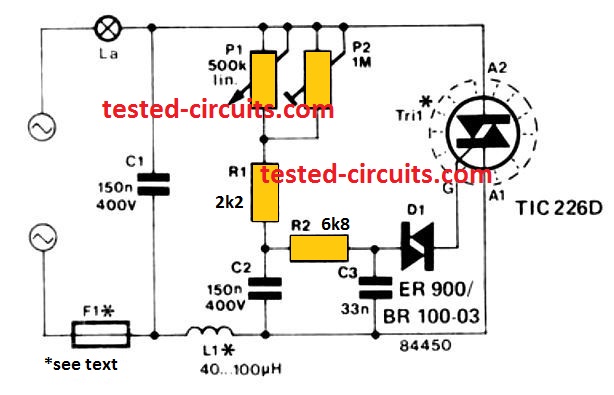
It includes one power triac, one diac and an RC configuration where the charging and discharging periods of capacitor C2 could be fixed with potentiometer P1. Electrical  surges are kept in check by capacitor C1 and inductor L1.

The calibration procedure requires adjusting P1 to optimum resistance and then fine tuning the preset P2 so that the lamp is just glowing.

If a lamp greater than 100 W is used make sure the triac is installed on a heatsink having a heat exchange rate of approximately 6 °C/W. For a 1000 W dimmer, suppressor coil L1 should be selected to have a 5 A (the inductance can be around 40 uH) and the fuse F1 could be rated at 6.3 amps.

You'll also like:

  • 1.  How to Build a Temperature to Voltage Converter Circuit
  • 2.  Simple Fluorescent Lamp Dimmer Circuit
  • 3.  Mains AC Surge Protector Circuits
  • 4.  How to Build a 3 Phase VFD Circuit
  • 5.  How Triacs Work: Explained
  • 6.  TL783 High-voltage Adjustable Regulator

About Admin

Hey friends, Thanks a bunch for stopping by this site! I am an engineer with a Bachelor of Engineering in Electronics and Telecommunication. One of my passions is gathering information from all sorts of electronics books and tutorials. I then take that information and compile it into a language that is super easy to understand. My goal is to make those complex electronics circuit concepts and technical terms much more accessible for all the new and budding electronics engineers out there. I can also design customized circuit diagrams as required by the users.
If you have any questions related to this field, please do not hesitate to drop a comment! I am always here and ready to help you out with any queries you might have. I cannot wait to hear from you!

Reader Interactions

Leave a Reply Cancel reply

Your email address will not be published. Required fields are marked *

Primary Sidebar

Categories

  • 3 Phase (4)
  • 8051 Microcontroller (1)
  • Arduino (11)
  • Audio and Amplifier (102)
  • Automation (8)
  • Battery Chargers (64)
  • Bicycle Projects (4)
  • Car and Motorcycle Projects (39)
  • Datasheets (10)
  • DIY Projects (5)
  • Electrical (15)
  • Free Energy (6)
  • Games Projects (2)
  • High Voltage (14)
  • Hobby Projects (30)
  • Household Circuits (2)
  • IC 555 Circuits (5)
  • Ignition Circuits (2)
  • Indicators (50)
  • Infrared (6)
  • Inverter Circuits (29)
  • Lights and Lamps (97)
  • Medical (8)
  • Meter and Tester Circuits (38)
  • Motor Driver (17)
  • New Circuits (56)
  • Oscillators (30)
  • Pets and Pests (5)
  • Power supply (80)
  • Protection Circuits (25)
  • PWM (9)
  • Remote Control (20)
  • Security and Alarm Circuit (48)
  • Sensors and Detectors (66)
  • Signal Processor (23)
  • Solar Controller Circuits (62)
  • SSR (3)
  • Temperature Controller (20)
  • Timer (25)
  • Transformerless (7)
  • Transmitters (12)
  • Tutorials (45)
  • UPS (2)
  • Voltage Regulators (57)
  • Water Sensor and Controller (29)
  • Home
  • Privacy Policy
  • Contact
  • Disclaimer
  • Copyright

© 2025 · Making Easy Circuits