In this article we’re going learn how we can create a two-relay, or two-stage, mains AC voltage stabilizer circuit. This handy little setup will help us control and regulate 220V or 120V mains voltages using a pretty straightforward circuit design.
Introduction to the Power Stabilizer Circuit
So in this power stabilizer circuit we’ are discussing, we have one relay that’s wired to select either the high or low tap from the stabilizer transformer at a specific voltage level. This is really important for ensuring that we get the right voltage output. Meanwhile the second relay is responsible for keeping the normal mains voltage switched on.
Now the moment there’s any kind of voltage fluctuation—like if the voltage spikes or dips—the circuit toggles and selects the appropriate HOT tap through the first relay contacts. This way we can maintain a stable output even when the input voltage isn’t behaving as it should!
Easy to Build with Effective Two-Stage Correction
The beauty of this simple power stabilizer circuit is that it’s really easy to build. Despite its simplicity it provides a solid two-stage correction of the input mains voltage, making it quite effective for our needs.
We’ll also discuss a simple method for converting a regular transformer into a stabilizer transformer, complete with circuit schematics to help us visualize everything.
Understanding Circuit Operation
Now if we take a look at the accompanying figure we can break down how the whole circuit operates with just a few key points.
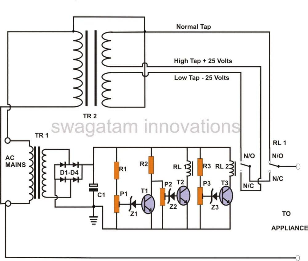
So the basic idea behind our setup here is to have relay #1 switch between two different extremes of mains voltage—specifically the high and low voltages that are considered unsuitable for our appliances. This is super important because we want to protect our devices from any voltage that could potentially cause damage.
How Relay #1 Works
By switching in this way, relay #1 can select an appropriately conditioned voltage from another relay through its normally closed (N/C) contacts. This means that when the voltage is outside the safe range, we can quickly switch to a safer option.
Wiring the Relay Contacts
Now, let’s talk about how we wire up these relay contacts. The contacts of our second relay which we’re calling relay #2 ensure that it selects the appropriate voltages from the stabilizer transformer. It keeps this voltage ready for relay #1 whenever it toggles in response to dangerous voltage levels.
When everything is running normally and the voltages are within safe limits, relay #1 stays activated and selects the normal voltage through its normally open (N/O) contacts. This keeps our appliances powered correctly.
The Role of Transistors T1 and T2
In our circuit we’ have got transistors T1 and T2 acting as voltage sensors. Relay #1 is connected to this configuration at the collector of T2. As long as everything is normal, T1 remains switched off. This means that T2 stays on, which keeps relay #1 activated and connects the normal AC supply to our appliance.
However if the voltage starts to rise above safe levels T1 begins to conduct slowly. Once it reaches a certain level—determined by how we set P1—T1 fully conducts, which shuts off T2 and consequently deactivates relay #1.
Switching to Corrected Voltage
When this happens, relay #1 immediately connects the corrected (lowered) voltage supplied by relay #2 through its N/C contacts to the output. This ensures that our appliances receive a safe level of voltage.
Now if there’s a drop in voltage instead both T1 and T2 will stop conducting which produces a similar result as before. But this time the supplied voltage from relay #2 to relay #1 will be higher allowing us to deliver the required corrected level of voltage.
The Function of Relay #2
Relay #2 gets energized by transistor T3 at a specific voltage level (as per the setting of P3) that falls between those two extremes of voltage we’re monitoring. Its contacts are wired to tap into the stabilizer transformer so that it can appropriately select the desired voltage when needed.
How to Assemble the Circuit
Now that we understand how everything works together, let’s talk about how we can actually put this circuit together. The construction process is pretty simple and can be done by following these steps:
- Cut a Piece of General Purpose Board: Start with a small piece of general-purpose board thats about 10 by 5 mm in size.
- Insert the Transistors: Begin by inserting the transistors first. Make sure to leave enough space between them so that we can accommodate all the other components around each one. Once they’re in place, solder their leads and cut off any excess.
- Add Remaining Components: Next insert all the other components into the board and interlink them with each other and with the transistors by soldering them in place. Its a good idea to refer to the circuit schematic during this step to ensure everything is oriented and placed correctly.
- Fix the Relays: Finally fix the relays onto the board to complete our assembly.
Next Steps
The next section will cover how to construct the power stabilizer transformer and outline the testing procedure for our circuit. Once these steps are completed successfully, we can integrate our tested circuit assembly with the appropriate transformers.
After everything is set up it’s a great idea to house the entire setup inside a sturdy metal enclosure so it’s protected and ready for operation!
Parts List
| Component | Value/Specification |
|---|---|
| R1, R2, R3 | 1K, 1/4W |
| P1, P2, P3 | 10K, Linear Presets |
| C1 | 1000uF, 25V |
| Z1, Z2, Z3 | 3V, 400mW Zener Diode |
| T1, T2, T3 | BC547B |
| RL1, RL2 | Relay 12V, SPDT, 400 Ohms |
| D1–D4 | 1N4007 |
| TR1 | 0–12V, 500mA |
| TR2 | 25–0–25V, 5A, with split center tap |
| Miscellaneous | General PCB, metallic enclosure, mains cord, socket, fuse holder, etc. |
How to Convert an Ordinary Transformer into a Stabilizer Transformer
So when it comes to stabilizer transformers we usually find that they are made to order and aren’t typically available ready-made in the market. This is primarily because we need multiple mains AC voltage taps—both high and low outputs—from these transformers and they are often tailored for specific applications. Because of this, it can be quite challenging to find them just sitting on a shelf somewhere.
Converting an Ordinary Transformer
In our current circuit we also need a power regulator transformer. However to make things easier for us during construction there’s a simple method we can use to convert an ordinary power supply transformer into a voltage stabilizer transformer.
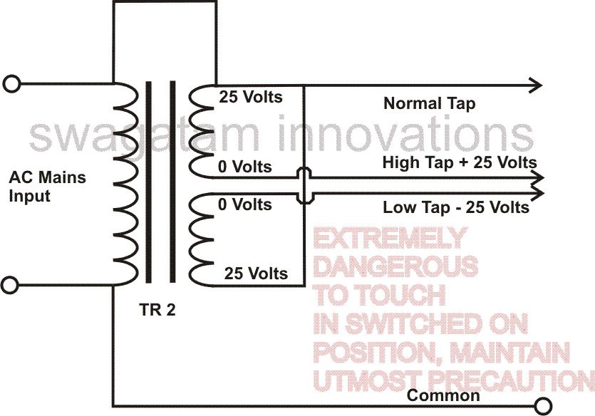
As shown in the accompanying figure what we need is a standard transformer that’s rated at 25-0-25 with a capacity of 5 amps. The key here is that the center tap of the transformer should be split so that the secondary side consists of two separate windings. After that it’s just a matter of connecting the primary wires to those two secondary windings as illustrated in the diagram.
By following this straightforward procedure we should be able to successfully transform an ordinary transformer into a stabilizer transformer which will be super handy for our current application!
How to Set Up the Unit
Now let’s talk about how we can set up this unit. We are going to need a variable power supply that provides 0-24V at 500mA for this setup procedure. Here’s how we can get it done step by step:
Understanding Voltage Fluctuations: We know that fluctuations in AC mains voltages will create corresponding fluctuations in DC voltage from our transformer. For example if we have input voltages of 210V, 230V, and 250V we can expect the equivalent DC voltages to be around 11.5V, 12.5V, and 13.5V respectively.
Setting the Presets: Based on those voltage levels, setting up the relevant presets becomes pretty straightforward.
Disconnecting Transformers: First things first—let’s keep both transformers TR1 and TR2 disconnected from the circuit for now.
Adjusting Potentiometers: We should set the sliders of P1, P2, and P3 to about the midway position.
Connecting the Power Supply: Now we can connect our external variable power supply to the circuit and adjust it to about 12.5 volts.
Activating RL2: Next, we’ll slowly start adjusting P3 until RL2 just activates.
Decreasing Voltage: After that let’s decrease the supply voltage to around 11.5 volts (at which point RL2 should deactivate). Now we can adjust P1 so that RL1 just deactivates as well.
Increasing Voltage Again: Gradually increase the supply voltage back up to about 13.5 volts—this should cause RL1 and RL2 to energize one after the other, which indicates that our settings are correct.
Final Adjustments: Finally, we’ll slowly adjust P2 so that RL1 deactivates again at this voltage level (13.5 volts).
Confirming Settings: To confirm everything is set up correctly let’s vary the input voltage back and forth between 11.5 volts and 13.5 volts. Here’s what we should see:
- RL1 should deactivate at both 11.5 volts and 13.5 volts but stay activated in between those voltages.
- RL2 should switch on above 12.5 volts and switch off below 12 volts.
Completing the Setup
And just like that our setting procedure is complete!
To finish things up with our power regulator unit we’ll connect the tested circuit with the appropriate transformers and then conceal everything inside a well-ventilated metallic enclosure as suggested on the previous page. This will help protect our setup while ensuring it operates safely and efficiently!
Leave a Reply