• Skip to main content
  • Skip to primary sidebar

Making Easy Circuits

Learn and build electronic circuits

You are here: Home / Security and Alarm Circuit / High Temperature Fire Alarm Circuit Using Transistors

High Temperature Fire Alarm Circuit Using Transistors

Last Updated on November 17, 2024 by Admin Leave a Comment

The post narrates the making of a simple high temperature fire alarm circuit using transistors only, and not with conventional heat sensors.

Though we don’t pay much heed to fire alarm usually, it is in fact a necessary factor that should be maintained as a de facto. Accident is unfortunate, but if you remain a bit cautious and maintain basic safety practices, you may save your property from the fire, if it ever happens to you.

While fire alarm circuit is a widely available tool in the market, many often retorts to building such component. Making a fire alarm tool is simple. All you need to gather are the components and follow specific procedure for installation to build the system.
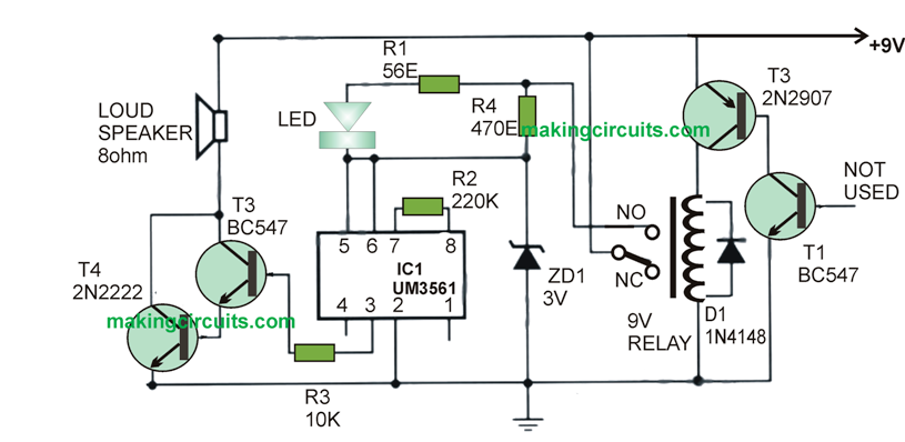
simple fire alarm circuit

Circuit Design of Fire Alarm Circuit


This fire-alarm circuit is designed in such a way that when the system receives temperature that exceeds to the permeable limit, this tool will automatically generate alarm.

Recommended Components

Resistors [1/4W +- 5%]

  • 66ohms – R1
  • 720K – R2
  • 10K – R3
  • 500 ohms – R4

Capacitors

1N4001 Diode – D1

Zener Diode 3V 0.5w – ZD1

3 Siren Sound Generator [UM3561] – IC1

Transistors are as follows

BC547 – Q1

BC547 – Q2

2N2907 – Q2

BC547 – Q3

2N2222 – Q4

9v Relay 100 ohms

8 ohms 1 watt Speaker

Procedure of Assembly

To define a proper tool, the proposed system will use the combination of silicon NPN transistor Q1 [BC109] and PNP Germanium Transistor Q2 [AC188]. The main reason to use both the components is for heat detection. The Q1 should be connected to Q2 and further Q2 should connect with RY1 relay.


The next part of the high temperature fire alarm circuit design process is with ICI-UM3561 where the IC that generates siren should be connected to a 3v power supply unit. In brief, connect Pin 5 and 6 of the IC to the power unit. During relay running procedure ensure that you have placed Pin 2 to the ground.

The R2 resistor over Pin 7 and Pin 8 operates to limit the oscillator frequency.

In order to boost signal from IC1 R4 resistor the output has to be sent from Q3 and Q4 transistors using the Darlington Compound process. The R4 is further connected to the Zener Diode series to control voltage supply on IC1. The R1 resistor is in series is connected to LED1 and also parallel to R4. Doing this would enable the tool working properly.


You'll also like:

  • 1.  Automatic LDR Switch Circuit with Flashing Lamp
  • 2.  Laser Operated Security Alarm Circuit
  • 3.  Capacitive Proximity Sensor Alarm Circuit
  • 4.  Anti-Burglar Home Lighting Circuit
  • 5.  Simple Electric Fencing Circuit
  • 6.  Powerful Fence Charger Circuit using CDI Ignition Coil

About Admin

Hey friends, Thanks a bunch for stopping by this site! I am an engineer with a Bachelor of Engineering in Electronics and Telecommunication. One of my passions is gathering information from all sorts of electronics books and tutorials. I then take that information and compile it into a language that is super easy to understand. My goal is to make those complex electronics circuit concepts and technical terms much more accessible for all the new and budding electronics engineers out there. I can also design customized circuit diagrams as required by the users.
If you have any questions related to this field, please do not hesitate to drop a comment! I am always here and ready to help you out with any queries you might have. I cannot wait to hear from you!

Reader Interactions

Leave a Reply Cancel reply

Your email address will not be published. Required fields are marked *

Primary Sidebar

Categories

  • 3 Phase (4)
  • 8051 Microcontroller (1)
  • Arduino (11)
  • Audio and Amplifier (102)
  • Automation (8)
  • Battery Chargers (64)
  • Bicycle Projects (4)
  • Car and Motorcycle Projects (39)
  • Datasheets (10)
  • DIY Projects (5)
  • Electrical (15)
  • Free Energy (6)
  • Games Projects (2)
  • High Voltage (14)
  • Hobby Projects (30)
  • Household Circuits (2)
  • IC 555 Circuits (4)
  • Ignition Circuits (2)
  • Indicators (50)
  • Infrared (6)
  • Inverter Circuits (29)
  • Lights and Lamps (97)
  • Medical (8)
  • Meter and Tester Circuits (38)
  • Motor Driver (17)
  • New Circuits (56)
  • Oscillators (30)
  • Pets and Pests (5)
  • Power supply (81)
  • Protection Circuits (25)
  • PWM (8)
  • Remote Control (20)
  • Security and Alarm Circuit (48)
  • Sensors and Detectors (66)
  • Signal Processor (23)
  • Solar Controller Circuits (61)
  • SSR (3)
  • Temperature Controller (20)
  • Timer (25)
  • Transformerless (7)
  • Transmitters (12)
  • Tutorials (45)
  • UPS (2)
  • Voltage Regulators (57)
  • Water Sensor and Controller (29)
  • Home
  • Privacy Policy
  • Contact
  • Disclaimer
  • Copyright

© 2025 · Making Easy Circuits