So this post breaks down how electret microphones actually work. Its got some super helpful diagrams and formulas that make everything a lot clearer.

What Exactly is a Microphone?
A microphone is this cool gadget that takes those faint sound vibrations we hear and turns them into tiny electrical pulses. Then these pulses can be amplified by a power amplifier and played through a loudspeaker which means we get to hear a louder version of the original sound.
Now when it comes to the most common and versatile type of microphone used in electronic circuits, we are talking about electret microphones. These little devices are compact, super sensitive, and they can pick up sound vibrations from pretty much any direction—yep that’s a full 360-degree range!
How Do Electret Microphones Work?
So at their core, these MICs consist of a diaphragm, a couple of electrodes, and an integrated JFET (that’s a type of transistor). The diaphragm is made from this thin Teflon material, which is also known as “electret,” hence the name electret microphone.
This electret has a fixed charge (let’s call it C) and is sandwiched between those two electrodes. Together, they form what we can think of as a sensitive variable capacitor. When sound waves hit the outer surface of this setup, it causes the capacitance between the electrodes to change.
Now as sound waves create variations in air pressure, one of the electrodes moves. This movement results in changes in capacitance across those capacitive plates. The instantaneous value of that varying capacitance is directly proportional to the sound pressure hitting the electret at any given moment.
Calculating MIC Capacitance
Now remember how I mentioned that the charge on the Teflon material is fixed? Because of that, the potential difference across our MIC capacitor can be expressed with this handy formula:
Q = C * V
In this equation:
Q represents the charge (which stays constant for our electret),
C stands for capacitance,
V indicates the voltage level or potential difference across those electrodes.
What this means is that the internal structure of our electret microphone behaves like an AC-coupled voltage source. Most electret mics come with an integrated JFET whose gate connects to that electret capacitor, acting as a buffer for it.
Since the charge of our capacitor is fixed, this buffer needs to have really high impedance—that is why we use a JFET in this case.
Internal Wiring Layout
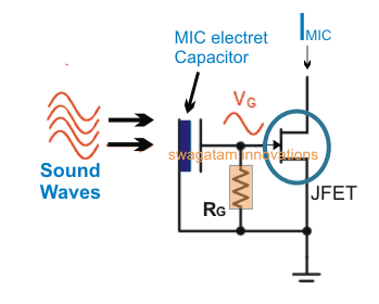
If you check out the diagram included in the post, you will see how everything is wired up inside a typical electret microphone. When sound vibrations hit that electret capacitor, they change its capacitance and produce a modulating voltage for the gate of the JFET (let us call it Vg). This modulation then alters how current flows through the drain/source of the JFET—this current is represented as Imic.
There’s also a stabilizing resistor (RG) connected internally across the gate and source of the JFET. This resistor has to be super high in value to prevent any unwanted shunting of the electret output for the JFET gate.
A Peek Inside an Electret MIC
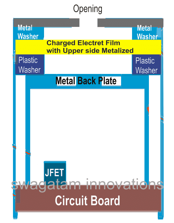
The image shows us a sectional view of an example electret mic. One electrode is created by layering metal over a charged polymer film. This metal layer connects to the mic case via a metallic washer. The case itself links up with the source lead of our internal JFET.
The second electrode—or other plate—uses a backside metal plate separated from that metalized film by a plastic washer. This plate connects to the gate terminal of our JFET. When sound waves hit this plate, they create strain on it, which changes how far apart those capacitive electrodes are from each other. This variation generates an equivalent potential difference between them.
That changing voltage across the drain of our JFET becomes our output signal for a preamplifier circuit stage. This stage amplifies everything further so we can hear an amplified version of those sound waves through a loudspeaker!
The Inner Workings of an Electret MIC
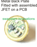
Lastly, there are some images showing all the actual parts used inside your typical electret mic


Leave a Reply