• Skip to main content
  • Skip to primary sidebar

Making Easy Circuits

Learn and build electronic circuits

You are here: Home / Water Sensor and Controller / How to Build a Greenhouse Motorized Water Diverter and Humidity Controller Circuit

How to Build a Greenhouse Motorized Water Diverter and Humidity Controller Circuit

Last Updated on November 17, 2024 by Admin Leave a Comment

In one of the earlier articles we figured out the providing of a greenhouse temperature controller circuit, right here we research just how the results might be improved by means of an automatic water valve actuator and humidity controller circuits.
The two designs might be recognized with the aid of the following article:
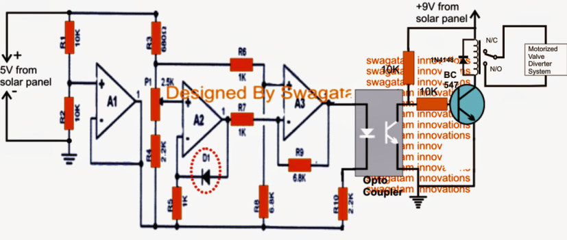
Talking about the very first circuit diagram below which happens to be essentially wired as a temperature sensor, is improved with a relay stage for immediately switching a motorized valve system or actuator which diverts cold water into the greenhouse water supply pipes in an event when the water temperature tends to rise above a fixed set level.


valvemotoroperatorcircuit
This circuit is pretty very much like the one that's described in one of the earlier content, for an extensive learn concerning the circuit info, you might think of the following post:
Greenhouse temperature regulator
The following design is a basic humidity sensor circuit which might be utilized for sensing and controlling greenhouse humidity levels.
As might be observed in the diagram, six NOT gates are linked in parallel for getting optimum performance from the devices.
The gates are all located as potential difference sensors across their input pins.
The 10M resistor at first holds the inputs to a low logic level since it's associated with the ground supply of the circuit.
The inputs are likewise shut down to the positive by means of an correctly etched PCB to form a closely set up copper mesh layout.
Provided that the humidity level is not beyond the unwanted threshold, the NOT gates inputs remain at a low logic state ensuing a high at their outputs which keeps the relay and a associated water sprayer initiated.
In spite of this, the moment the humidity level tends to cross the set high level it tends to build a low resistance across the copper mesh PCB forcing the inputs of the NOT gates to turn out to be higher in potential until it flips and inverts the individual outputs to logic low, which often switches OFF the relay and the water sprayer for the present time.
The 10M resistance might be refined for setting-up the most wanted cut off humidity threshold level.
The LED ON implies the toggling of the relay and vice versa.


greenhouseautowatersprayercircuit


You'll also like:

  • 1.  IC 555 Dry Run Protection Circuit
  • 2.  Dry Run Protector Circuits using Transistors only
  • 3.  How to Make a Industrial Tank water fill/drain controller circuit
  • 4.  Automatic Garden Watering Circuit
  • 5.  Car Tank Water Sensor Circuit without Corrosion
  • 6.  How to Make a Light Activated Water Level Controller Circuit

About Admin

Hey friends, Thanks a bunch for stopping by this site! I am an engineer with a Bachelor of Engineering in Electronics and Telecommunication. One of my passions is gathering information from all sorts of electronics books and tutorials. I then take that information and compile it into a language that is super easy to understand. My goal is to make those complex electronics circuit concepts and technical terms much more accessible for all the new and budding electronics engineers out there. I can also design customized circuit diagrams as required by the users.
If you have any questions related to this field, please do not hesitate to drop a comment! I am always here and ready to help you out with any queries you might have. I cannot wait to hear from you!

Reader Interactions

Leave a Reply Cancel reply

Your email address will not be published. Required fields are marked *

Primary Sidebar

Categories

  • 3 Phase (4)
  • 8051 Microcontroller (1)
  • Arduino (11)
  • Audio and Amplifier (102)
  • Automation (8)
  • Battery Chargers (64)
  • Bicycle Projects (4)
  • Car and Motorcycle Projects (39)
  • Datasheets (10)
  • DIY Projects (5)
  • Electrical (15)
  • Free Energy (6)
  • Games Projects (2)
  • High Voltage (14)
  • Hobby Projects (30)
  • Household Circuits (2)
  • IC 555 Circuits (5)
  • Ignition Circuits (2)
  • Indicators (50)
  • Infrared (6)
  • Inverter Circuits (29)
  • Lights and Lamps (97)
  • Medical (8)
  • Meter and Tester Circuits (38)
  • Motor Driver (17)
  • New Circuits (56)
  • Oscillators (30)
  • Pets and Pests (5)
  • Power supply (80)
  • Protection Circuits (25)
  • PWM (9)
  • Remote Control (20)
  • Security and Alarm Circuit (48)
  • Sensors and Detectors (66)
  • Signal Processor (23)
  • Solar Controller Circuits (62)
  • SSR (3)
  • Temperature Controller (20)
  • Timer (25)
  • Transformerless (7)
  • Transmitters (12)
  • Tutorials (45)
  • UPS (2)
  • Voltage Regulators (57)
  • Water Sensor and Controller (29)
  • Home
  • Privacy Policy
  • Contact
  • Disclaimer
  • Copyright

© 2025 · Making Easy Circuits