• Skip to main content
  • Skip to primary sidebar

Making Easy Circuits

Learn and build electronic circuits

You are here: Home / SSR / How to Connect Opto-Coupler with a Triac

How to Connect Opto-Coupler with a Triac

Last Updated on March 30, 2020 by Admin 2 Comments

In this post we will learn the correct method of integrating an opto-coupler with a triac so that the triac is driven effectively with optimal current and also remains perfectly isolated from the triggering input.

Overview

Nearly every electronic component is a victim of imperfect working due to temperature change.

Triacs are not as vulnerable, but even they stop working at lower temperatures.

This can be traced back to the need for a higher gate current in triacs at lower temperatures.

Opto-couplers, which are the most common way of triggering triacs, cannot supply currents of that magnitude.

The circuit here solves this problem how to connect an opto coupler through a transistor amplifier stage to maintain the required gate current at all temperatures.

how to connect opto coupler with triac

How the Circuit Works

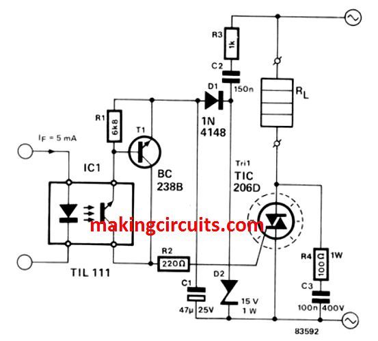
The transistor T1, that bumps the opto-coupler signal above the necessary level, forms the amplifier.

The capacitor C2 has a double function. On one hand, it is used as a 'dropping' reactance to prevent dissipation almost completely in the drive circuit.

On the other, it eliminates the circuit putting a DC load on the mains supply.

Resistor R3 keeps the initial current surge due to switching on under the safety threshold.

The supply voltage for the drive circuit must also be rectified and smoothed, as done by D1 and C1 respectively, as it comes directly from the mains. The D2 zener diode is used to stabilize the circuit supply at 15 V.

C1 starts discharging through transistor T1 as T1 starts conducting. As a result, a gate current of about 40 mA is supplied the triac gate.

The discharge time, as well as the trigger pulse, is limited under a millisecond. The triac is shielded from high peaks by the R4/C3 RC network.

The above explained design clearly explains how to configure an opto-coupler with a triac through a intermediate transistor driver stage for an effective switching of the triac through an opto-coupler.

You'll also like:

  • 1.  How to Make a 2V DC Solid State Relay (SSR) 100 Amps
  • 2.  Solid State Relay (SSR) Circuit Using Triac

About Admin

Hey friends, Thanks a bunch for stopping by this site! I am an engineer with a Bachelor of Engineering in Electronics and Telecommunication. One of my passions is gathering information from all sorts of electronics books and tutorials. I then take that information and compile it into a language that is super easy to understand. My goal is to make those complex electronics circuit concepts and technical terms much more accessible for all the new and budding electronics engineers out there. I can also design customized circuit diagrams as required by the users.
If you have any questions related to this field, please do not hesitate to drop a comment! I am always here and ready to help you out with any queries you might have. I cannot wait to hear from you!

Reader Interactions

Comments

  1. Aleksandr says

    April 29, 2022 at 1:29 pm

    This scheme is not working. A ballast capacitor can provide less than 10mA of source current (divide the mains voltage by the capacitor reactance). Therefore, it is impossible to obtain a constant gate current of 40mA. The aluminum capacitor will discharge once when the optocoupler is opened, which will cause the triac to open for one half-cycle of voltage. To open the triac in the next half-cycles, the capacitor will no longer have the necessary charge and it will not be able to charge.

    Reply
    • admin says

      May 10, 2022 at 9:25 am

      You can increase the value of C2 to get more current. The capacitor will charge and discharge correctly due to the presence of the 15V zener diode.

      Reply

Leave a Reply Cancel reply

Your email address will not be published. Required fields are marked *

Primary Sidebar

Categories

  • 3 Phase (4)
  • 8051 Microcontroller (1)
  • Arduino (11)
  • Audio and Amplifier (102)
  • Automation (8)
  • Battery Chargers (64)
  • Bicycle Projects (4)
  • Car and Motorcycle Projects (39)
  • Datasheets (10)
  • DIY Projects (5)
  • Electrical (15)
  • Free Energy (6)
  • Games Projects (2)
  • High Voltage (14)
  • Hobby Projects (30)
  • Household Circuits (2)
  • IC 555 Circuits (5)
  • Ignition Circuits (2)
  • Indicators (50)
  • Infrared (6)
  • Inverter Circuits (29)
  • Lights and Lamps (97)
  • Medical (8)
  • Meter and Tester Circuits (38)
  • Motor Driver (17)
  • New Circuits (56)
  • Oscillators (30)
  • Pets and Pests (5)
  • Power supply (80)
  • Protection Circuits (25)
  • PWM (9)
  • Remote Control (20)
  • Security and Alarm Circuit (48)
  • Sensors and Detectors (66)
  • Signal Processor (23)
  • Solar Controller Circuits (62)
  • SSR (3)
  • Temperature Controller (20)
  • Timer (25)
  • Transformerless (7)
  • Transmitters (12)
  • Tutorials (45)
  • UPS (2)
  • Voltage Regulators (57)
  • Water Sensor and Controller (29)
  • Home
  • Privacy Policy
  • Contact
  • Disclaimer
  • Copyright

© 2025 · Making Easy Circuits