In this post we will learn the correct method of integrating an opto-coupler with a triac so that the triac is driven effectively with optimal current and also remains perfectly isolated from the triggering input.
Overview
Nearly every electronic component is a victim of imperfect working due to temperature change.
Triacs are not as vulnerable, but even they stop working at lower temperatures.
This can be traced back to the need for a higher gate current in triacs at lower temperatures.
Opto-couplers, which are the most common way of triggering triacs, cannot supply currents of that magnitude.
The circuit here solves this problem how to connect an opto coupler through a transistor amplifier stage to maintain the required gate current at all temperatures.
How the Circuit Works
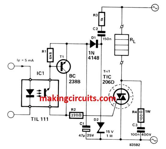
The transistor T1, that bumps the opto-coupler signal above the necessary level, forms the amplifier.
The capacitor C2 has a double function. On one hand, it is used as a 'dropping' reactance to prevent dissipation almost completely in the drive circuit.
On the other, it eliminates the circuit putting a DC load on the mains supply.
Resistor R3 keeps the initial current surge due to switching on under the safety threshold.
The supply voltage for the drive circuit must also be rectified and smoothed, as done by D1 and C1 respectively, as it comes directly from the mains. The D2 zener diode is used to stabilize the circuit supply at 15 V.
C1 starts discharging through transistor T1 as T1 starts conducting. As a result, a gate current of about 40 mA is supplied the triac gate.
The discharge time, as well as the trigger pulse, is limited under a millisecond. The triac is shielded from high peaks by the R4/C3 RC network.
The above explained design clearly explains how to configure an opto-coupler with a triac through a intermediate transistor driver stage for an effective switching of the triac through an opto-coupler.
Dear AleksandrCancel,
I tried your schematic, but unfortunately i cant get it to work properly. I used a BTA06 triac, and a BC337-25 transistor instead. I addes a db3 diac between the gate and the 220R resistor. But it still does not have the power yo regulate a 100w ac fan, are a 55w dc motor. I linked the optocoupler to an arduino, an it does neem to react to the script. What am i doing wrong, are how can i change the schematic so i can use it for the fan are dc motor.
I look forward to your response.
Kind regards,
D. Smith
Hey Smith,
The circuit was originally designed for AC phase-angle control using a TRIAC, therefore it cannot properly control a DC motor. A TRIAC requires AC zero crossings to turn OFF, so for DC motor speed control you would need a PWM MOSFET controller instead.
Also, the DB3 DIAC should not be necessary in this design and may actually interfere with the TRIAC gate triggering. I would suggest removing it and testing the original configuration first.
The BC337 is a suitable replacement for the BC238B, but please verify the BTA06 pinout carefully because its terminal arrangement may differ from the original TIC206D.
Finally if your 100W fan is a capacitor-run or electronically controlled type, phase-angle control may not provide satisfactory torque or speed regulation. In that case a different control method may be required.
Does the fan run at full speed when the optocoupler input is driven continuously at maximum current? That information will help determine whether the issue is related to TRIAC triggering or the type of motor being controlled.
This scheme is not working. A ballast capacitor can provide less than 10mA of source current (divide the mains voltage by the capacitor reactance). Therefore, it is impossible to obtain a constant gate current of 40mA. The aluminum capacitor will discharge once when the optocoupler is opened, which will cause the triac to open for one half-cycle of voltage. To open the triac in the next half-cycles, the capacitor will no longer have the necessary charge and it will not be able to charge.
You can increase the value of C2 to get more current. The capacitor will charge and discharge correctly due to the presence of the 15V zener diode.