In this article we are basically learning one very easy and straight method how we can get or make 220V AC from just a small 12V DC battery or power source. So here we are not using any difficult and costly design. We are using a simple boost circuit which works using one oscillator system and one inductor coil. This whole thing is done using our old and very popular timer IC that is the IC 555.
Now we all already know right that normal inverters do this job also—they take low DC and make it into big AC voltage like our home mains. But those inverters are normally full of many components and are very complicated and also they can be costly because of transformer and many other things.
So then to solve this and make the thing easy we can just use one oscillator boost converter circuit which uses a MOSFET. It is a much simpler way. If we do not care about waveform shape too much then like no need pure sine wave or anything then this method is really cheap and simple and fast to build.
How the Circuit Works:
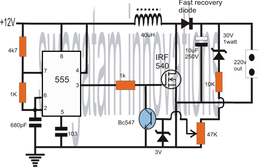
So now if we look at the diagram of the circuit then we can clearly see everything is moving around the IC 555. This IC is configured in astable mode which means it is working like a pulse generator or oscillator. The frequency of the pulse it gives is set by two resistors 4k7 1k and one capacitor of 680pF.
That 1k resistor you can play with or experiment with for adjusting duty cycle properly. Then the output from the IC comes from pin number 3. This output is connected straight to the gate pin of an N channel MOSFET.
So when we power ON the circuit then the IC starts giving positive pulses from pin number 3 and those pulses go and switch ON the MOSFET fully. So now every time the MOSFET gets ON then it pulls the heavy 12V current through the coil straight to ground through itself.
But now we know one important thing that coil or inductor never allows sudden change in current right. It will always oppose. So when suddenly the MOSFET gets OFF then the coil becomes angry and tries to push out all the energy it stored in the form of high voltage. That high voltage comes out as back EMF and reaches the output side.
This high voltage can reach around 220V or whatever coil is designed for. And that is how we get our AC like 220V output at the terminal.
This full ON OFF action happens very fast at the oscillator frequency and that makes a continuous 220V supply at the output terminal.
Now for safety and voltage control we have also added one small transistor BC547 along with its base resistors and preset. This part is added so that we do not allow the voltage to cross 220V. So you can adjust the 47k preset to fix the voltage level. Even if the coil gives more back EMF or the battery voltage changes a bit then still the output will not go above 220V because of this BC547 feedback.
The MOSFET which we use can be any type that can handle 30V and around 50 amps like for example the NTD4302 type. Also the coil wire should be thick no compromise because it must carry high current 30 amp or more without getting hot.
Circuit Diagram
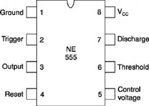
IC 555 Pinout Details
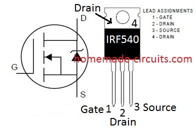
Mosfet IRF 540 Pinout Details
Full Construction Process of 12V to 220V Boost Converter Circuit
Now we are going to make this whole circuit step by step. So we will collect all the parts first then we will build it on a breadboard or a PCB.
- Collect All the Components
Here is the full list of components you must collect before starting:
- IC 555 timer – 1 piece
- N channel MOSFET IRF540 – 1 piece
- NPN transistor BC547 – 1 piece
- Inductor coil – 40 microhenry (40uH) – must be thick wire
- Resistors – 4k7, 1k (2 pieces), 10k, 47k – all 1/4 watt
- Capacitors – 680pF, 10nF (marked as 103), 10uF/250V electrolytic
- Fast recovery diode – 1 piece (example UF4007)
- Zener diode – 3V 1/2 watt
- High watt resistor – 30V zener series resistor – 1 watt type
- Output 220V socket – 1 piece
- 12V battery or 12V DC power supply
- Wires and general purpose PCB or breadboard
- Start Assembling the Oscillator Section (IC 555 Part)
First we will make the oscillator which is the heart of the circuit.
Take IC 555 and place it on the breadboard or PCB.
Connect pin 8 to +12V supply line
Connect pin 1 to ground
Now connect 4k7 resistor from pin 8 to pin 7
Then connect 1k resistor from pin 7 to pin 6
Put 680pF capacitor from pin 6 to ground
Short pin 6 and pin 2
Connect a 10nF (marked as 103) capacitor from pin 5 to ground
Connect pin 4 directly to +12V
Now your IC 555 will start giving pulses from pin 3 automatically. This is the pulse we will use to drive the MOSFET.
- Drive Stage for the MOSFET
Take a 1k resistor and connect one side to pin 3 of IC 555
Connect the other side of this resistor to gate of IRF540 MOSFET
Connect source of the MOSFET to ground
Connect drain of MOSFET to one side of the inductor coil
- Add the Boost Coil and Diode
Now take your 40uH coil and connect one end to +12V supply
Connect the other end of the coil to drain of the MOSFET
At the same drain point connect a fast recovery diode with its cathode going to output filter capacitor
The anode of diode goes to drain of MOSFET (same point)
- Connect the Output Capacitor and Zener Clamping
Take 10uF/250V electrolytic capacitor and connect its positive to diode cathode
Negative of capacitor goes to ground
At same positive line connect one high watt 30V zener diode in series with a 1 watt resistor
Then connect this to a 10k resistor which goes to base of BC547
- Add the Feedback Control Transistor Section
This section will control the output voltage to make sure it does not cross 220V
Connect 3V zener diode across base and ground of BC547 transistor (anode to ground cathode to base)
Connect emitter of BC547 to ground
Connect a 47k preset resistor between positive of output capacitor and the base of BC547 (through the zener)
Collector of BC547 goes to the gate line of MOSFET (through the 1k already present)
This means if output voltage goes above limit then this BC547 will conduct and pull down the gate signal of the MOSFET and stop it from boosting more voltage.
- Output Connection
From the positive end of the output capacitor take two wires and connect it to the 220V AC socket
Negative line of capacitor should be connected to ground of the circuit
- Powering the Circuit
Now take a good 12V battery or a 12V DC supply which can give at least 5 amps current
Connect +12V to the supply rail and ground to the negative rail of the board
As soon as you power it ON the IC 555 will start oscillating
MOSFET will start switching
Coil will begin boosting and you will get around 220V AC-like output at the socket
Final Notes and Safety
Be very careful while testing the output side because it carries high voltage
Make sure the coil wire is thick and good quality or else it will heat up
All grounds must be connected properly
Use a heatsink for the MOSFET if it gets hot
Always test with a multimeter before connecting any real load
Boa tarde!
Observei que o pino 1 do C.I 555 do referido conversor D.C/A.C não aparece no desenho do diagrama. Ele pode ficar flutuando ou necessita ser conectado no terra do sistema proposto?
Thank you for notifying the mistake, pin#1 certainly needs to be connected to ground, otherwise the circuit will not work…