Through an unusual fundamental nature, cold electricity is produced by stimulating the flow of positive charge in the line through the negative line of an LC network. This leads to the development of an entropic negative charge across the inductor, which subsequently flows into the capacitor as "cold" electricity.
It is referred to be "cold" because it operates in an open circuit without releasing any heat.
The post that follows describes how to create cold electricity with a straightforward circuit that charges a capacitor at a high voltage without drawing any power from the linked battery source.
How only a Single Inductor Works
The fascinating phenomena of producing cold electricity employing only a single inductor, a few switches, and a supply voltage source was previously shown in a YouTube video.
At first glance, it seemed to be just a buck-boost setup, although a closer examination revealed that a phenomenon quite peculiar was occurring within the circuit.
How the Cold Electricity Phenomenon Works
We're going to examine the scenario and attempt to understand how the fascinating chilly electricity was generated. A single pair of SPDT switches, a high voltage capacitor, an inductor, and a 24V DC supply make up the extremely simple circuit seen in the diagram below.
The capacitor is shown to be charged to a voltage equal to the inductance back emf value in this instance within seconds as both switches are swiftly shut and released simultaneously.
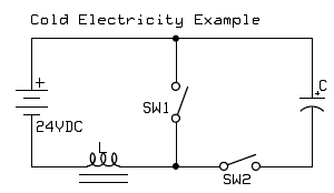
- L = 800 turns bifilar coil around a ferrite core, about 30 ohms
- C= 30μF, 4000VDC
The two of the switches in the circuit above must be swiftly shut and released simultaneously.
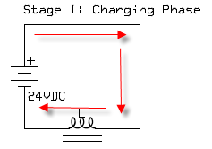
The inductor is designed to conserve power as magnetic field energy at the same time the switches are locked. This would create a high resistance over the battery, preventing the inductor from using any current.
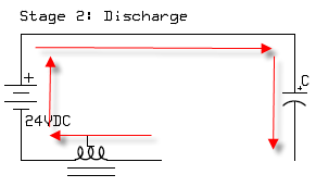
However immediately as the switches were opened, it was evident that the inductor was providing a high voltage to charge the capacitor.
How the Inductor Internal Energy Saturation Works
The concern that emerges revolves around how the switches remaining open and the circuit not creating a closed loop for the capacitor to charge may allow the potential difference to go across the capacitor.
The impact in this case, according to the author, is caused by electrical energy coming into interaction with the resistance (an opened switch), in which the resistance is saturated by the current within the inductance.
Another publication provides an alternative explanation:
How the Singularity Situation is being Created
Because the shift in current is incapable of being stopped through the inductor, a singularity scenario is formed in the circuit when the switches close and open rapidly.
There is a voltage multiplication across the coil just before the magnetic field over the inductor could decrease.
Without the pulling any current through the battery, this increased voltage charges the capacitor.
Understanding The Ferroresonance Effect
One explanation for this might pertain to the ferroresonance effect, which means that the potential enters the inductor through an unusual negative path as the core is saturated, affecting the positive charge and causing a negative entropic field to be induced within the inductor, which subsequently charges the capacitor.
Leave a Reply