Here, I will explain how to construct a 220V operated basic heater controller circuit at a current rate of 25 amps employing a standard triac-based dimmer switch circuit in this post.
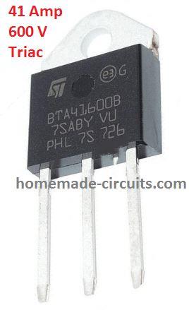
Improved Snubber-less Triacs
Controlling heaters that can go up to 5000 watts is no walk in the park, it demands some pretty strict specifications for the control unit to ensure everything runs safely and effectively.
But thanks to the new snubber-less Triacs and Diacs, cranking out heater controllers that can handle these hefty watt levels has become a whole lot easier these days.
Now let’s investigate into a straightforward yet totally fitting setup that you can use to whip up a 1500-watt heater controller circuit.
Understanding the Circuit Diagram
How the Triac/Diac AC Controller Works
The way this circuit is put together is pretty typical, the wiring looks a lot like what you’d find in your regular light dimmer switch setups.
You’ll notice the standard triac and diac arrangement which is essential for getting the triac to switch on and off.
So whats the deal with the diac?
Wel, it’s this small little device that only lets current flow through it once a certain voltage threshold is crossed.
The resistors and capacitors linked with the diac are picked out so that they only allow it to fire while the sine wave stays below a specific voltage level.
Once that sine wave goes above this set point, the diac stops conducting, which in turn switches off the triac.
Since our heater (the load) is wired in series with the triac, it too will follow suit, turning off and on based on what the triac is doing.
This means that the triac only conducts during particular parts of the input sine voltage wave, resulting in an output where the AC gets chopped into smaller bits.
This chopping lowers the overall RMS (Root Mean Square) value of the voltage reaching the heater, depending on how we’ve configured those resistors and capacitors around the diac.
The pot (potentiometer) you see in the diagram is there for controlling how much power goes to the heater element.
The higher you set that resistance the longer it takes for the capacitor to charge and discharge.
This delay keeps both the triac and load off for longer stretches of time during each AC sine cycle which means less average voltage gets to the heater, keeping its temperature cooler.
On the flip side if you adjust that pot to lower resistance values, then that capacitor charges and discharges quicker.
This quickening speeds up everything leading to a longer average on-time for the triac.
Consequently this gives more average voltage to the heater making it heat up more due to this increased voltage across it via the triac.
Circuit Diagram
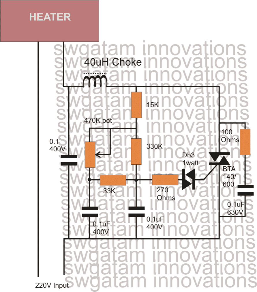
Parts List
| Component Type | Specification | Quantity |
|---|---|---|
| Resistors | 1/4 watt, 5% CFR | |
| 15k | 1 | |
| 330k | 1 | |
| 33k | 1 | |
| 270 ohms | 1 | |
| 100 ohms | 1 | |
| Potentiometer | 470k linear or 220k linear | |
| Capacitors | 0.1uF/250V | 2 |
| 0.1uF/630V | 2 | |
| Semiconductors | DB-3 | 1 |
| Triac | BTA41/600 | |
| Inductor | 40uH, 30 amp (optional) |
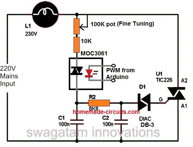
Utilizing Arduino PWM for heat controlling
An external Arduino PWM feed may also be used to successfully build the aforementioned basic 220V dimmer switch control employing the straightforward technique below:
Leave a Reply