The publish clearly shows a very easy 3 phase generator circuit design that makes use of just three transistors and a few passive components for starting the preferred three phase output.
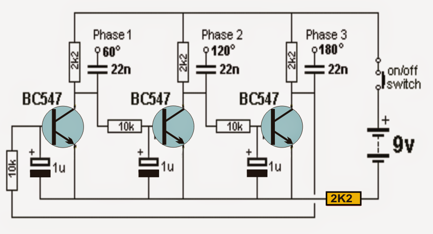
Talking about the schematic above we are able to notice three identical transistor stages set up in a cross combined manner, owning parallel RC timing constants across their bases.
The 10k resistor along with the 1u capacitor fundamentally turn out to be accountable of offering the needed delay impact for producing the meant 3 phase signals with 120 degree phase shift.
When ever power is turned on, the phases may look like to go through a locked sequence, nevertheless considering that all the capacitors are not able to have a exactly same value, the one which has a shade lower value than the other charges up first, initiating a sequential conduction across the transistor.
Let's believe that on account of inconsistency in values, the middle transistor base capacitor becomes charged first, this permits the middle transistor to perform first which often grounds the base of the extreme right transistor avoiding it from carrying out for that immediate situation, but at the same time the base capacitor of the left or the right transistor also gets charged in conjunction which forces the middle transistor to turn off and release the right transistor conduction.
The above mutual push and pull process encourages and settles into a constant sequential train of conduction across the transistors provoking the meant three phase signal pattern to become across the collectors of the transistors.
Because of the constant charge and discharge design of the caapcitrs, the subsequent signal shape is a pure sine wave.
The 2K2 resistor demonstrated in yellow strangely turns into critical in beginning the 3 phase signal generation series, without which the circuit appears to stall suddenly.
As I have said before the degree of stage might be modified by altering the RC values across the bases of the transistors, here it's set up to generate a 120 degree phase shift.
Hey how can amplifay so it is more powerful so that I can, for example, drive a bldc motor
This circuit cannot be used to drive a BLDC motor even after amplification, because BLDC motors require precise 3 phase signal timing for its correct working and therefore only dedicated BLDC driver ICs must be used.
I just tried to built it and it works like a charm! 🙂 I only have a 2-Channel Oscilloscope douh, but I checked/calculated the Pulse (RP)-phases between the outputs and everything checks out.
Great work!
Thanks for the feedback, glad it worked!!
Luca,
In a simulator, all three capacitors and all three transistors, and all three base resistors will be exactly identical, so all stages will charge exactly the same and the circuit runs in lockstep. In real life, this is impossible, so the circuit quickly settles into the expected 3-phase operation. You need to make one capacitor just slightly different from the others (maybe 1% difference will do it). Allow enough run-time for the imbalance to propagate through (possibly dozens of cycles of oscillation).
Hi i’m Luca. I’ve tried to build this circuit in Qucs but doesn’t work like the description. All three signals are in phase with each other.
Maybe i’ve wrong something during simulation, can anyone help me?
I’ve wired three-star resistor on the outputs and i’ve measured the voltage across they.
I’ve add the ground connection on the negative pole of the battery.
I hope i have write clear sentences.
Thank to each comment.
Luca
Hi, the above circuit is a tested circuit. You can see the waveform which was measured from a practical circuit. If you build it and test it with an oscilloscope you are going to get correct results.
Muy fascinante éstos circuitos, estoy muy agradecido por estas ilustraciones.
Thank you, I appreciate your response….