• Skip to main content
  • Skip to primary sidebar

Making Easy Circuits

Learn and build electronic circuits

You are here: Home / Water Sensor and Controller / How to Make a Light Activated Water Level Controller Circuit

How to Make a Light Activated Water Level Controller Circuit

Last Updated on February 17, 2018 by Admin Leave a Comment

The light triggered water level controller circuit discussed the following post carries the good thing about being corrosion free and considerably trustworthy rather than the traditional moisture sensor type of water sensors.

One slight problem with this LDR based sensor is that the tank interior usually ought to be activated by some form of light source for instance a bulb or a LED.

A LDR sensor is designed with a IC 741 opamp and changed thoroughly such that the light falling over the LDR continues the pin3 of the IC low in accordance with a targeted light source and with use with pin2 set voltage.

In an occasion the light across the LDR is disrupted, persuades an disturbance across the pinouts of the IC activating the opamp output to go high and trigger the hooked up relay and the load.

In the current light triggered water level controller circuit, an LDR is employed and located across the the area of the tank where the level is intended to be supervised, or a relay is intended to be turned on in accordance with a rise in the water level.


water2Blevel2Bsensor


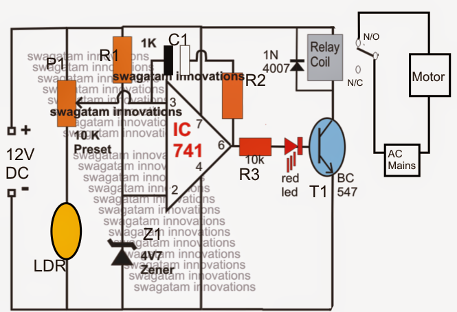
Providing you will discover an lack of water across the sensing zone, the LDRs go through the incident light (situated from the opposite side, inside the tank) which usually continues pin3 of the IC low, on the other hand when water begins rising and will probably cover the LDR in the path, reverts to a high at pin3 of the IC which instantaneously guides the opamp output to go high starting the relay and the pump.

A hysteresis control feedback resistor across the opamps (R2/C1)) make certain that the once the scenario is imagined it keeps latched for a few certain time as well as the pump motor is in a position to drive until the water has achieved the bottom of the tank. The time for which the opamp continues latched could be dependent upon adjusting the feedback resistor hooked up between the output and the input pins of the opamp.

You'll also like:

  • 1.  Simple Water Level Alarm Circuit using IC 555
  • 2.  IC 555 Automatic water Level Controller Circuit
  • 3.  How to Build a Greenhouse Motorized Water Diverter and Humidity Controller Circuit
  • 4.  Flood Detector Warning Alarm Circuit
  • 5.  Simplest Water Level Controller Circuit with Buzzer
  • 6.  Simple Water Sensor Circuit with Alarm

About Admin

Hey friends, Thanks a bunch for stopping by this site! I am an engineer with a Bachelor of Engineering in Electronics and Telecommunication. One of my passions is gathering information from all sorts of electronics books and tutorials. I then take that information and compile it into a language that is super easy to understand. My goal is to make those complex electronics circuit concepts and technical terms much more accessible for all the new and budding electronics engineers out there. I can also design customized circuit diagrams as required by the users.
If you have any questions related to this field, please do not hesitate to drop a comment! I am always here and ready to help you out with any queries you might have. I cannot wait to hear from you!

Reader Interactions

Leave a Reply Cancel reply

Your email address will not be published. Required fields are marked *

Primary Sidebar

Categories

  • 3 Phase (4)
  • 8051 Microcontroller (1)
  • Arduino (11)
  • Audio and Amplifier (102)
  • Automation (8)
  • Battery Chargers (64)
  • Bicycle Projects (4)
  • Car and Motorcycle Projects (39)
  • Datasheets (10)
  • DIY Projects (5)
  • Electrical (15)
  • Free Energy (6)
  • Games Projects (2)
  • High Voltage (14)
  • Hobby Projects (30)
  • Household Circuits (2)
  • IC 555 Circuits (5)
  • Ignition Circuits (2)
  • Indicators (50)
  • Infrared (6)
  • Inverter Circuits (29)
  • Lights and Lamps (97)
  • Medical (8)
  • Meter and Tester Circuits (38)
  • Motor Driver (17)
  • New Circuits (56)
  • Oscillators (30)
  • Pets and Pests (5)
  • Power supply (80)
  • Protection Circuits (25)
  • PWM (9)
  • Remote Control (20)
  • Security and Alarm Circuit (48)
  • Sensors and Detectors (66)
  • Signal Processor (23)
  • Solar Controller Circuits (62)
  • SSR (3)
  • Temperature Controller (20)
  • Timer (25)
  • Transformerless (7)
  • Transmitters (12)
  • Tutorials (45)
  • UPS (2)
  • Voltage Regulators (57)
  • Water Sensor and Controller (29)
  • Home
  • Privacy Policy
  • Contact
  • Disclaimer
  • Copyright

© 2025 · Making Easy Circuits