The electronic thermostat mentioned here may be used to control the room temperature by correctly switching (activating and off) a heating device.
Operating particulars of electronic thermostat
The circuit applies a thermistor NTC (negative temperature coefficient) as the sensor device.
- Assuming that the ambient temperature continues greater than the value prefixed by the potentiometer, the relay in the same manner continues to be inactivate and the red LED could also be noticed brightened.
- In a situation of the ambient temperature becoming lesser than the set value, the relay is turned on and the green LED is activated.
The potentiometer ought to be precisely changed in an effort to acquire the required outcomes.
To adjust the suggested transistor thermostat circuit, the NTC is enclosed inside a glass tube and its leads are closed out by way of long wires in order that it could be situated over the wanted location for the essential sensing.
The circuit is focused by positioning the thermistor glass tube alongside a mercury thermometer inside a container containing with melting ice water, along with the following method its located at ambient temperature ultimately next to a gas burner for utilizing all the setting levels.
In each of the previously discussed situations, the level exactly where the green LED just brightens is positioned by softly manipulating the pot knob toward the maximum and standing it with a line over the knob dial in an effort to produce the suitable temperature calibrations, these kinds of markings are then correctly labelled with the particular temperatures which are usually registered during this time on the linked thermometer.
The circuit process is fairly uncomplicated allowing it to be recognized by examining each transistor cut off and provoking states.
For assuming the NTC resistance is incredibly high (when the ambient temperature is low) leads to the transistor T1 to get into saturation offered the potentiometer setting enables this.
Taking into consideration the above scenario is permitted the transistors T1 T2 T3 and T4 saturate or simply trigger the relay.
The relay applied could also be a double contact and each time it is turned on two functions are carried out, one pair of contacts to switch the LEDs as well as the other to turn on the heater or the wanted load.
The capacitor C1 assures immediate modifications in the value of the NTC.
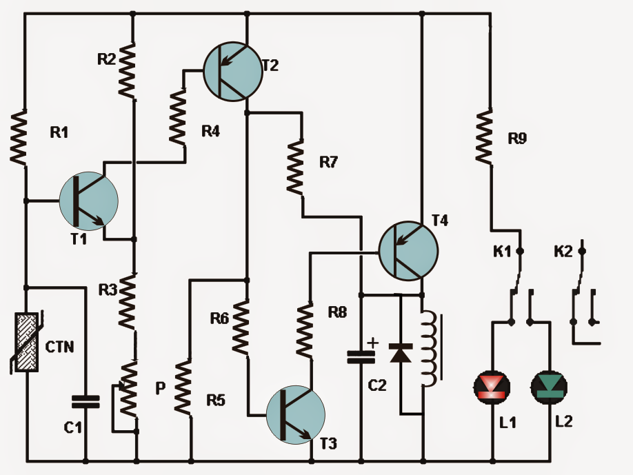
Bill Of Material for the above transistor thermostat circuit:
- Resistors: R1, R4, R6: 10K, R2: 12K, R3: 6.8K, R5: 33K, R7: 470K, R8: 2.2K, R9: 560 ohms.
- Potentiometer: Linear 10K.
- NTC: Negative temperature coefficient 10K.
- Capacitors: C1: 100nF, C2: 47uF, 10V (electrolytic capacitor).
- LEDs: 1 red, 1 green
- Transistors T1 and T3: 2N2222, T2: 2N2907, T4: 2N2905
- Relay: 12V DPDT.
Leave a Reply