• Skip to main content
  • Skip to primary sidebar

Making Easy Circuits

Learn and build electronic circuits

You are here: Home / High Voltage / How to Make a Solar Fence Charger Circuit

How to Make a Solar Fence Charger Circuit

Last Updated on February 17, 2018 by Admin 1 Comment

A Fence charger or energizer is a system which is often used for charging(electrifying) a fence or a boundary to be able to safeguard the inside premise from human or animal interventions. Considering that these types of limitations are mainly of huge fields and parks, are usually removed from the major cities, and running them by means of a few alternative choice turns into be far better than from utility grids which can turn out to be tough to obtain in such type of isolated areas.

The circuit of a solar electric fence charger described right here is not going to rely on standard power source for functioning, somewhat gets it 24/7 from a self continuous solar power change set up.

The circuit is very easy to figure out.

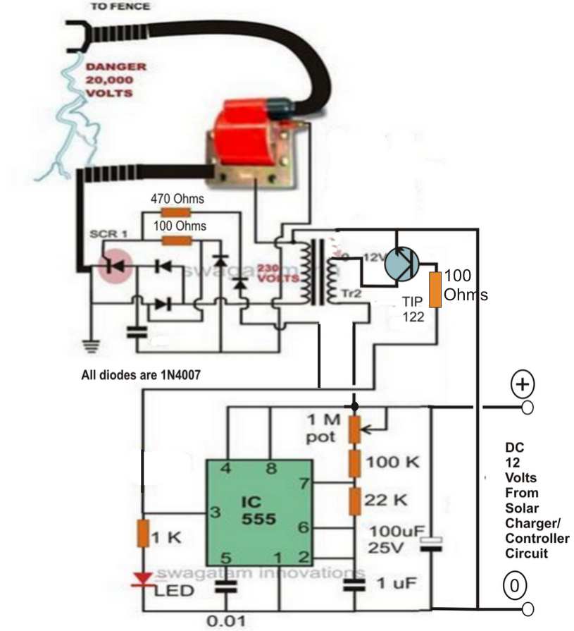
The fence charger circuit is actually a switching circuit which includes a couple of diodes and a high voltage capacitor.

The diodes can be used for correcting the AC from a small step up transformer so that it gets kept inside the high voltage capacitor.

When this voltage gets to a specific guideline, the SCR fires and releases the whole stored voltage inside the capacitor.

The above releasing of the capacitor is conducted or else thrown out inside the primary section of an automobile ignition coil.

The unexpected dumping of the above high voltage inside the ignition coils primary, steps up the rise into a number of a large number of volts into the secondary winding of the ignition coil.

This stepped up voltage is utilized for activating the fences or the limitations accordingly.

In spite of this the above procedures needs an AC input at the levels of around 100 to 220volts.

This voltage is produced by surely processing the input DC from a solar panel set up.

The voltage from the solar panel is first managed to an appropriate level and then it's useful for running a initiating circuit.

The activating circuit contains a IC 555 oscillator which switches the voltage received from the solar panel controller into the transformers input, so that the output from the transformer produces the needed 220V AC for powering the ignition circuit.

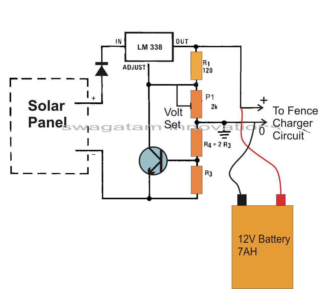
The solar panel output also charges a small 12V/7AH battery so that the power can be utilized after dusk, when sun energy is inaccessible.

solarfencechargercircuit


The above circuit can be operated by way of the following solar panel current controlled battery charger circuit:


solarbatterychargercircuit


You'll also like:

  • 1.  MPPT Solar Charger with 3-Step Charger Circuit
  • 2.  How to Correctly Calculate Solar Panel, Inverter, Battery Charger
  • 3.  How to Hookup a Solar Panel System – Living of the Grid
  • 4.  Make this Solar Battery Charger Circuit using IC 7812
  • 5.  Make Solar Voltage Battery Charger Controller using LM338 IC
  • 6.  How to Desalinate Sea Water Rapidly

About Admin

Hey friends, Thanks a bunch for stopping by this site! I am an engineer with a Bachelor of Engineering in Electronics and Telecommunication. One of my passions is gathering information from all sorts of electronics books and tutorials. I then take that information and compile it into a language that is super easy to understand. My goal is to make those complex electronics circuit concepts and technical terms much more accessible for all the new and budding electronics engineers out there. I can also design customized circuit diagrams as required by the users.
If you have any questions related to this field, please do not hesitate to drop a comment! I am always here and ready to help you out with any queries you might have. I cannot wait to hear from you!

Reader Interactions

Comments

  1. Bob says

    June 6, 2023 at 7:23 am

    What would need to be changed to run at 120 volts AC instead of229 volts?

    Reply

Leave a Reply Cancel reply

Your email address will not be published. Required fields are marked *

Primary Sidebar

Categories

  • 3 Phase (4)
  • 8051 Microcontroller (1)
  • Arduino (11)
  • Audio and Amplifier (102)
  • Automation (8)
  • Battery Chargers (64)
  • Bicycle Projects (4)
  • Car and Motorcycle Projects (39)
  • Datasheets (10)
  • DIY Projects (5)
  • Electrical (15)
  • Free Energy (6)
  • Games Projects (2)
  • High Voltage (14)
  • Hobby Projects (30)
  • Household Circuits (2)
  • IC 555 Circuits (5)
  • Ignition Circuits (2)
  • Indicators (50)
  • Infrared (6)
  • Inverter Circuits (29)
  • Lights and Lamps (97)
  • Medical (8)
  • Meter and Tester Circuits (38)
  • Motor Driver (17)
  • New Circuits (56)
  • Oscillators (30)
  • Pets and Pests (5)
  • Power supply (80)
  • Protection Circuits (25)
  • PWM (9)
  • Remote Control (20)
  • Security and Alarm Circuit (48)
  • Sensors and Detectors (66)
  • Signal Processor (23)
  • Solar Controller Circuits (62)
  • SSR (3)
  • Temperature Controller (20)
  • Timer (25)
  • Transformerless (7)
  • Transmitters (12)
  • Tutorials (45)
  • UPS (2)
  • Voltage Regulators (57)
  • Water Sensor and Controller (29)
  • Home
  • Privacy Policy
  • Contact
  • Disclaimer
  • Copyright

© 2025 · Making Easy Circuits