• Skip to main content
  • Skip to primary sidebar

Making Easy Circuits

Learn and build electronic circuits

You are here: Home / Motor Driver / How to make a Temperature Triggered DC Fan Speed Controller Circuit

How to make a Temperature Triggered DC Fan Speed Controller Circuit

Last Updated on February 17, 2018 by Admin Leave a Comment

This fan speed controller functions by sensing the temperature of the engine and is appropriately useful for the initiating. As the temperature raises so does the speed of the fan motor and vice versa.
Procedure of the offered temperature managed fan might be recognized given below:
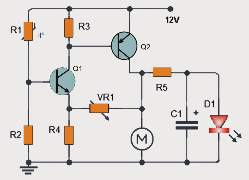
The speed of the DC motor changes as the temperature boosts which can be transformed into a correspondingly rising voltage and utilized between its terminals.
To calculate temperature thermistor (R1) to be positioned as close as possible to the place where you would like him to feel temperature is utilized.
In the diagram, one can possibly notice that the thermistor (R1) and the resistor (R2) are being used to develop a voltage divider network. It is strongly recommended that the value of R2 is just about roughly one tenth of the value of R1.
As the temperature thermistor value diminishes it brings about the transistor Q1 to saturate more difficult correspondingly.
Considering that the collector of Q1 is hooked up to the base of Q2, the voltage at the base of Q2 also replies to the above and diminishes
The voltage diminishes at the base of Q2 which turns into saturated more difficult, producing the collector-emitter voltage (VCE) to lower thus increasing the voltage on the collector terminal of the motor.
The maximum speed of the motor is going to be somewhat lower than its calculated requirement.
To in addition, it might not be essentially required for accurate circuit operation, to understand the temperature to be able to control engine speed an LED can be utilized as presented in the diagram. This LED will correspondingly get brighter as the engine speed increases.


Parts List
R1: 15K thermistor
R2: 1.5K
R3: 1K
R4: 47
R5: 680
VR1: preset 22K
C1: 100uF/25V
Q1: 2N2712 (NPN) or equivalent
Q2: BD140 (PNP) or equivalent
D1 LED
M: Motor DC brushed or brushless
Note: The DC motor may be not the same as a computer motor. Ensure that the current rating of the motor is not going to surpass the rating of the transistor Q2. (maximum current 1.5 amps). It is strongly recommended not to go over 1 amp and use sink.

You'll also like:

  • 1.  How to Build a 3 Phase Brushless (BLDC) Motor Driver Circuit
  • 2.  How to Make a Office Call Bell Network Circuit with LED Monitor
  • 3.  How to Make a Cellphone Jammer Circuit Explored
  • 4.  Protecting Motor from Overcurrent Conditions
  • 5.  PWM Amplifier Circuit
  • 6.  40 LED Bicycle Light Circuit

About Admin

Hey friends, Thanks a bunch for stopping by this site! I am an engineer with a Bachelor of Engineering in Electronics and Telecommunication. One of my passions is gathering information from all sorts of electronics books and tutorials. I then take that information and compile it into a language that is super easy to understand. My goal is to make those complex electronics circuit concepts and technical terms much more accessible for all the new and budding electronics engineers out there. I can also design customized circuit diagrams as required by the users.
If you have any questions related to this field, please do not hesitate to drop a comment! I am always here and ready to help you out with any queries you might have. I cannot wait to hear from you!

Reader Interactions

Leave a Reply Cancel reply

Your email address will not be published. Required fields are marked *

Primary Sidebar

Categories

  • 3 Phase (4)
  • 8051 Microcontroller (1)
  • Arduino (11)
  • Audio and Amplifier (102)
  • Automation (8)
  • Battery Chargers (64)
  • Bicycle Projects (4)
  • Car and Motorcycle Projects (39)
  • Datasheets (10)
  • DIY Projects (5)
  • Electrical (15)
  • Free Energy (6)
  • Games Projects (2)
  • High Voltage (14)
  • Hobby Projects (30)
  • Household Circuits (2)
  • IC 555 Circuits (4)
  • Ignition Circuits (2)
  • Indicators (50)
  • Infrared (6)
  • Inverter Circuits (29)
  • Lights and Lamps (97)
  • Medical (8)
  • Meter and Tester Circuits (38)
  • Motor Driver (17)
  • New Circuits (56)
  • Oscillators (30)
  • Pets and Pests (5)
  • Power supply (81)
  • Protection Circuits (25)
  • PWM (8)
  • Remote Control (20)
  • Security and Alarm Circuit (48)
  • Sensors and Detectors (66)
  • Signal Processor (23)
  • Solar Controller Circuits (61)
  • SSR (3)
  • Temperature Controller (20)
  • Timer (25)
  • Transformerless (7)
  • Transmitters (12)
  • Tutorials (45)
  • UPS (2)
  • Voltage Regulators (57)
  • Water Sensor and Controller (29)
  • Home
  • Privacy Policy
  • Contact
  • Disclaimer
  • Copyright

© 2025 · Making Easy Circuits