• Skip to main content
  • Skip to primary sidebar

Making Easy Circuits

Learn and build electronic circuits

You are here: Home / Lights and Lamps / How to Make Digital Christmas Candle Light Circuit

How to Make Digital Christmas Candle Light Circuit

Last Updated on February 17, 2018 by Admin Leave a Comment

The article discuses a in sequence moving onto 25 LED timer circuit which might be started on the 1st day of December in order that each LeD brightens on each day until the 25th of December (on Christmas) when all the 25 LeD can be watched illuminated.

Christmas2Bcandles


Christmas2Bcandle2Bcircuit

IC1-----IC2 = 4017

T1, T2 = BC547

pin15 capacitor, resistor are 0.22uF and 1M respectively

rest of the resistors are all 4k7

The Design

The offered digital Christmas candle light timer circuit is generally applied by configuring the above two circuits by making use of the following recommendations:

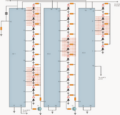
The left diagram above means the 25 LED timer circuit that may be required to light up in sequence from day#1 when the circuit is activated, until the 25he of December when the final 25th LeD lights up, at the rate of 1 LED per day.

The level is established by wiring or cascading three IC 4017 ICs. The clock inputs of all the three ICs are rigged with the clock output of the right hand side circuit making use of IC 4060, whose pin3 output is intended to be linked with the pin14 of all the IC 4017.

R1, R2 and C1 of IC1 are measured such that pin3 delivers a high clock after a period of specifically 24 hours, the moment the technique is activated.

This 24 hour clock pulse is given to the pin14 of the three 4017 ICs in order that a high logic shifts in sequence from pin3 of IC1 every single day until the 25th day when the last LED at pin#1 of IC3 lights up.

The circuit is operated choosing two 9V rechargeable batteries, one being attached perfectly with the supply pins of the IC steps even though the other attached by way of a 1K resistor.

The battery that is certainly plugged in by way of a 1K resistor is effectively linked with the circuit and confirms that the ICs are usually driven with the minimum essential current, in an effort to preserve the memory of the ICs in case that the main battery obtains exhausted in the midst of the 25 day period and while the user takes away it for recharging and replacing it back.

You'll also like:

  • 1.  Chasing LED Trouser Circuit
  • 2.  100 watt Current Controlled LED Driver Circuit
  • 3.  Simple High Power LED Flashlight Circuit
  • 4.  Circuit for a Simple, High-Efficiency LED Torch
  • 5.  18 LED Chaser Circuit Diagram Explained
  • 6.  20 watt, 5 watt Fluorescent Lamp Inverter Circuit

About Admin

Hey friends, Thanks a bunch for stopping by this site! I am an engineer with a Bachelor of Engineering in Electronics and Telecommunication. One of my passions is gathering information from all sorts of electronics books and tutorials. I then take that information and compile it into a language that is super easy to understand. My goal is to make those complex electronics circuit concepts and technical terms much more accessible for all the new and budding electronics engineers out there. I can also design customized circuit diagrams as required by the users.
If you have any questions related to this field, please do not hesitate to drop a comment! I am always here and ready to help you out with any queries you might have. I cannot wait to hear from you!

Reader Interactions

Leave a Reply Cancel reply

Your email address will not be published. Required fields are marked *

Primary Sidebar

Categories

  • 3 Phase (4)
  • 8051 Microcontroller (1)
  • Arduino (11)
  • Audio and Amplifier (102)
  • Automation (8)
  • Battery Chargers (64)
  • Bicycle Projects (4)
  • Car and Motorcycle Projects (39)
  • Datasheets (10)
  • DIY Projects (5)
  • Electrical (15)
  • Free Energy (6)
  • Games Projects (2)
  • High Voltage (14)
  • Hobby Projects (30)
  • Household Circuits (2)
  • IC 555 Circuits (4)
  • Ignition Circuits (2)
  • Indicators (50)
  • Infrared (6)
  • Inverter Circuits (29)
  • Lights and Lamps (97)
  • Medical (8)
  • Meter and Tester Circuits (38)
  • Motor Driver (17)
  • New Circuits (56)
  • Oscillators (30)
  • Pets and Pests (5)
  • Power supply (81)
  • Protection Circuits (25)
  • PWM (8)
  • Remote Control (20)
  • Security and Alarm Circuit (48)
  • Sensors and Detectors (66)
  • Signal Processor (23)
  • Solar Controller Circuits (61)
  • SSR (3)
  • Temperature Controller (20)
  • Timer (25)
  • Transformerless (7)
  • Transmitters (12)
  • Tutorials (45)
  • UPS (2)
  • Voltage Regulators (57)
  • Water Sensor and Controller (29)
  • Home
  • Privacy Policy
  • Contact
  • Disclaimer
  • Copyright

© 2025 · Making Easy Circuits