The content below details two basic 12V, 1 Amp switch mode power supply (SMPS) circuits that utilize the highly dependable VIPerXX IC from ST microelectronics.
With the introduction of modern ICs and circuits, the traditional iron transformer power supplies are definitely becoming outdated.
Today, power supplies are more compact, smaller, and efficient in their operation. In this article, we talk about a simple switch mode power supply circuit that can be constructed at home to obtain a smooth, ripple-free 12 V DC output.
The VIPer22A IC from ST Microelectronics has enabled the creation of highly efficient and small SMPS power supply units with a minimal amount of electronic components.
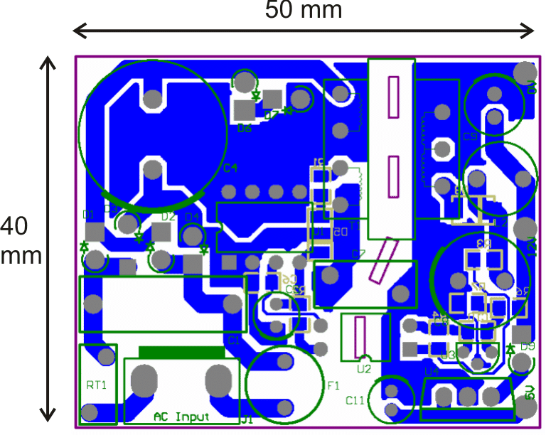
The image shows that the circuit is quite tiny when considering the amount of power it can produce. Its dimensions measure 50 by 40 mm.
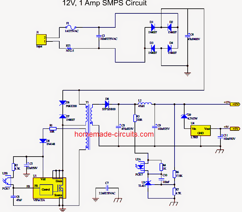
The circuit diagram is simple to comprehend, let's analyze it based on the following points:
Making an SMPS using VIPer22A
Examining the image, it's clear that the arrangement doesn't consist of numerous stages or components.
The typical procedure involves, rectifying the incoming mains AC using standard 1N4007 diodes arranged in a bridge configuration.
The high voltage DC that has been rectified is purified with a high voltage capacitor.
The crucial next step involves the outstanding chip VIPer22A made by, ST Microelectronics.
The Integrated Circuit acts as the sole oscillator, and generates a frequency of approximately 100 KHz in the primary coil of the ferrite E core transformer.
The IC is extremely durable and has internal protection against sudden voltage surges and other voltage-related component risks.
The IC also includes internal overheat protection making it nearly indestructible.
Due to minimal eddy current losses the voltage induced at the input is reduced at the output winding, allowing for around 1 amp of current to be provided by a small ferrite transformer.
The voltage is approximately 12 with the coil specifications provided, and the current is approximately 1 amp.
Additionally there is a unique feedback circuitry in the circuit to uphold a high level of protection and conserve power.
The opto-coupler is activated when there are abnormal circuit conditions, allowing for the implementation of a feedback loop.
When the output voltage exceeds the established threshold, the feedback loop activates and sends an error signal to the IC FB input.
The IC quickly enters a correction mode and turns off the input to the primary winding until the output is back within the normal range.
Circuit Diagram
PCB Layout
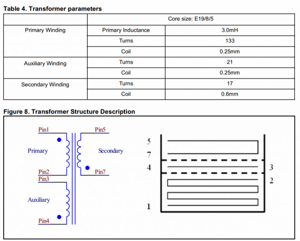
Transformer Winding Data
Parts List

2) Another 12V 1 amp simple SMPS using IC TNY267

How it Works
The basic smps circuit illustrated above utilizes the well-known TNY267 small switch IC. A small IC operates as a switching oscillator with a MOSFET at 120V to 220V needing only a ferrite transformer and lower Vdd voltage to set up.
The simplicity of the design allows us to quickly understand the functioning details just by looking at the schematic.
The initial voltage is obtained from a stabilizing network with a 180V zener diode and a fast recovery diode BA159 after rectifying the 220V mains with a 1N4007 diode and a 10uF/400V filter capacitor.
Once the IC receives the voltage, it starts to oscillate and the internal mosfet immediately begins to switch the ferrite transformer primary at the set frequency.
Because it is a flyback design the secondary circuit also begins to conduct electricity when the primary circuit is turned off thanks to mutual induction, producing the necessary 12V output voltage.
The voltage might not be stable so an opto-coupler feedback is used and the connection is set up with the exclusive shut down pinout 4 of the IC.
This makes sure the output stays at a constant 12V and does not go beyond 1 amp.
Data of the winding of a transformer
Winding the transformer is a simple process that can be accomplished in the following way. Remember that the black dots show where to begin winding the transformer, this must be strictly adhered to during the winding process.
The main coil is wound with 36 SWG copper wire in up to 150 turns, while the secondary coil is wound with 26 SWG wire in approximately 12 to 15 turns.
The core may consist of a typical E19 ferrite core with a bobbin containing a central core cross section area of about 4.5mm by 4.5mm.
Leave a Reply