• Skip to main content
  • Skip to primary sidebar

Making Easy Circuits

Learn and build electronic circuits

You are here: Home / Audio and Amplifier / IC SN76477 based Enhanced Machine Gun (MG) Sound Generator Circuit

IC SN76477 based Enhanced Machine Gun (MG) Sound Generator Circuit

Last Updated on May 30, 2025 by Admin 2 Comments

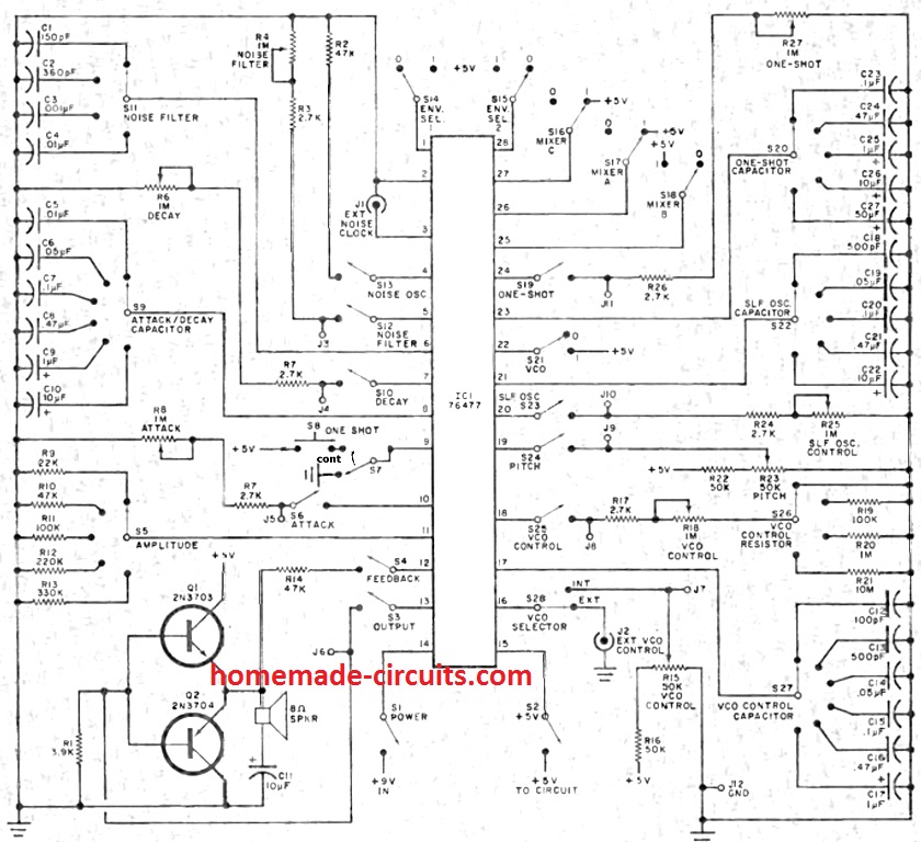
Bird chirps, freight trains, racetrack engines, sirens, phasor guns, organs (with additional push buttons), wind, jungle, and other noises may all be produced with this sound generator chip.

Extremely low-frequency oscillation (SLF), voltage controlled oscillator (VCO), and noise oscillator are its three oscillators. You are free to choose any three of these combinations.

The gunshot acoustic was much more realistic thanks to the sound decay mechanism. I have an old data sheet with several audio applications that I have discovered.

In order to provide other sounds, I intend to add several rotary switches with configurable capacitors.

Apparently are two sizes for this chip, which buyers should be informed of. The smaller version is the SN76477NF, and the regular big size is the SN76477.

It would prove rather challenging to make use of the NF size socket without a printed circuit board or an adaptor.

After a long wait, I was thrilled when I got two of the bigger SN76477 sound chips. I had no success finding someone who has used this chip to make a mg sound when searching the Internet.

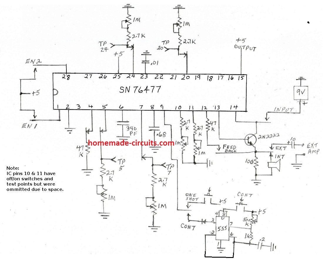
In the end, I added a 555 timerchip and connected its pulsating output to pin 9 of the one-shot circuit.

To choose between the continuous mg sound and the one-shot sound, I built an SPDT switch. I have both sound kinds controlled by push buttons. SN76477 is being powered by a 9 volt battery that I have.

I'm powering the 555 IC with the 5 volt output which this chip regulates. I can use an ohm-meter between every point of testing and "G," or ground, and switch off the wiring to the ic pins thanks to the test points. Every potentiometer has a resistance setting that I can adjust.

In addition, I installed a connection for my 200-watt amplifier. I have yet to give this a try.

I actually had to cut down the lengthy video I had intended to give you an overview of each feature since my iPhone claimed it was too big. I'm currently collaborating on the updated schematic and will email it shortly.

This is the updated experimenter's board schematic, which fixes the pin 9 mistake. To enable one-shot noises, provide a positive pulse to pin 9.

To disable all sounds, operate a switch in parallel to the push button and set it to +5.To solve the issue, I updated the design to include an SPDT switch on pin 9.

Enhanced Machine Gun (MG) Sound Generator Circuit using IC  SN76477

In the future, I plan to incorporate rotary switches for selecting different capacitors and expand my sound library. In order to bring together the sound oscillators, three spst switches must be additionally added on pins 25, 26, and 27.

You'll also like:

  • 1.  How to Build a 2 x 50V 350W SMPS Circuit
  • 2.  Very Low Frequency (VLF) Converter Circuit
  • 3.  Music Stroboscope Circuit
  • 4.  Precision Guitar Tuner Circuit
  • 5.  High Power Headphone Amplifier Circuit
  • 6.  Scratch And Rumble Filter Circuit

About Admin

Hey friends, Thanks a bunch for stopping by this site! I am an engineer with a Bachelor of Engineering in Electronics and Telecommunication. One of my passions is gathering information from all sorts of electronics books and tutorials. I then take that information and compile it into a language that is super easy to understand. My goal is to make those complex electronics circuit concepts and technical terms much more accessible for all the new and budding electronics engineers out there. I can also design customized circuit diagrams as required by the users.
If you have any questions related to this field, please do not hesitate to drop a comment! I am always here and ready to help you out with any queries you might have. I cannot wait to hear from you!

Reader Interactions

Comments

  1. Greg Quiring says

    December 4, 2024 at 7:49 am

    I’ve got a chip marked sn76477n but it has a .07″pitch like the NF. Maybe mismarked. The original chip from 1978 was much bigger. Having trouble finding a socket for the new one and at a reasonable price. How did you connect yours?

    Reply
    • admin says

      December 6, 2024 at 6:35 pm

      I soldered the chip directly on perfboard, and luckily everything worked nicely…

      Reply

Leave a Reply Cancel reply

Your email address will not be published. Required fields are marked *

Primary Sidebar

Categories

  • 3 Phase (4)
  • 8051 Microcontroller (1)
  • Arduino (11)
  • Audio and Amplifier (102)
  • Automation (8)
  • Battery Chargers (64)
  • Bicycle Projects (4)
  • Car and Motorcycle Projects (39)
  • Datasheets (10)
  • DIY Projects (5)
  • Electrical (15)
  • Free Energy (6)
  • Games Projects (2)
  • High Voltage (14)
  • Hobby Projects (30)
  • Household Circuits (2)
  • IC 555 Circuits (4)
  • Ignition Circuits (2)
  • Indicators (50)
  • Infrared (6)
  • Inverter Circuits (29)
  • Lights and Lamps (97)
  • Medical (8)
  • Meter and Tester Circuits (38)
  • Motor Driver (17)
  • New Circuits (56)
  • Oscillators (30)
  • Pets and Pests (5)
  • Power supply (81)
  • Protection Circuits (25)
  • PWM (8)
  • Remote Control (20)
  • Security and Alarm Circuit (48)
  • Sensors and Detectors (66)
  • Signal Processor (23)
  • Solar Controller Circuits (61)
  • SSR (3)
  • Temperature Controller (20)
  • Timer (25)
  • Transformerless (7)
  • Transmitters (12)
  • Tutorials (45)
  • UPS (2)
  • Voltage Regulators (57)
  • Water Sensor and Controller (29)
  • Home
  • Privacy Policy
  • Contact
  • Disclaimer
  • Copyright

© 2025 · Making Easy Circuits