We all might have usually observed laser alarm system as an important part of security solution specifically for a location which ought to get hi-level security.
Starting from a museum conserving priceless historical possession; to a safety bank vault; and even in thriller flicks where the protagonist is seen on and often tied in the ray of red light beams, while attempting to achieve a safe vault; one is well familiar with the use of laser light beams. In reality additionally it is regarded as a safety device even just in household these days to defend against burglary or robbery.
A laser beam is not a basic beam, but has the effectiveness to react when faced a interruption. This indicates if the light ray gets disrupted with any objects, the photodiode obtains resistance which often trigger an alarm. The laser alarm system is a cost effective option with regards to use of power, as the recipient requires power supply less than 10 mA on average. Establishing a laser alarm system is comparatively simpler as the laser and the receiver may be setup in one box, on a single power input.
Below is a circuit design diagram which demonstrates the flow of a laser alarm system.
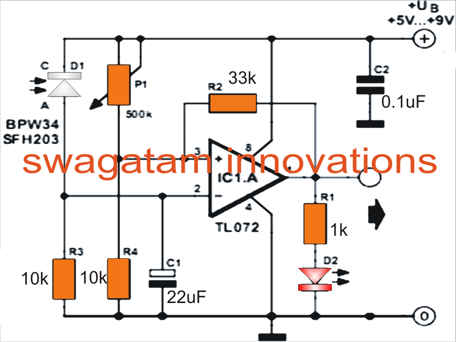
Talking about circuit diagram it is noticed that a TL072 op-amp (IC1.A) is set up as a voltage comparator, used in between the adjustable voltage driver P1/R4 and the light-dependent voltage which comprises of photodiode D1 and R3 - a fixed resistor. As the laser beam gets a interruption from a foreign agent, the voltage on comparator pin falls to 2 below that at pin 3, therefore allowing the agent swing to positive voltage supply and allow an alarm circumstance.
As the laser alarm can identify any foreign agents, so is the alarm could be set in a more advanced fashion, in which can bypass accidental interrupts from agents, like an insect. This is achieved as the Resistor R2 offers a level of hysteresis, therefore reduce oscillation when two comparator input voltage rests in almost identical condition. To be able to set a faster reply technique, it may be accomplished by lowering the value to 1 µF.
A laser beam method is simpler to build, whichever as a single or a separate entity. If a single box is preserved to setup the alarm, then it is to be made sure that the photodiode can’t have direct contact with the laser beam. Building the components and the circuit in a breadboard, it ought to be installed in a black box having a hole. A black consuming straw ought to go through the hole to permit light flow from the direction of the laser beam to enter. Establishing the system correctly tends to make the laser beam behave despite direct sunlight, as it are not able to have an effect on the operation of the photodiode.
Leave a Reply