An LC oscillator is a circuit we use to turn a DC supply into an AC output waveform.
So now this output can show many waveform shapes and many frequencies, however it depends on what we are building. You may see complex patterns or a clean sine wave, therefore the use decides the shape.
Moreover LC oscillators are seen in test equipment like function generators, since these can produce sinusoidal, square, sawtooth, triangular signals, and also long repeating pulses with fixed or changing width. But we also notice LC oscillators are very common in RF circuits, because they give good phase noise performance and the design stays simple.
Basics Of Oscillators
At the most basic level, an oscillator looks like an amplifier using positive feedback, we also call this regenerative feedback, so now the signal keeps reinforcing itself in phase. However in circuit design, one big trouble comes when amplifiers start oscillating on their own, but when we design an oscillator, then we actually want that behavior and we want it controlled.
So what happens is that oscillators work by compensating energy loss in a resonant circuit, usually made using inductors and capacitors or both together. When DC energy is pushed into this resonant network at the right frequency, then oscillation starts. In simple words, an oscillator is a positive feedback amplifier that gives an output frequency without needing any external AC input.
Essential Characteristics Of Oscillators
Now for any circuit to act as an oscillator, we must satisfy three conditions, no shortcut here. First is Amplification, so we need a device that increases signal level. Second is Positive Feedback, so energy must come back into the input in the correct direction. Third is Frequency-Determining Network, so the oscillation frequency stays fixed.
When an oscillator begins working, then it usually uses a small-signal feedback amplifier whose open-loop gain is equal to or slightly higher than unity, then oscillation can grow. If oscillation must never stop, then the average loop gain should remain at unity. Since this condition must hold, we include reactive components along with an active device like an Op-Amp or a BJT.
How Oscillator Circuits Behave
Oscillator circuits behave very differently from normal amplifiers, because they do not need any external AC signal at all. So they directly convert DC energy into AC energy at a frequency decided by the resonant network. When this happens, then the circuit produces a self-sustaining periodic waveform, usually a stable sinusoidal output, and it just keeps running.
Understanding a Basic Oscillator Feedback Circuit
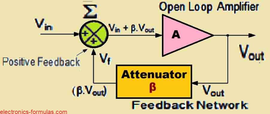
Calculating Gain Of The Oscillator Circuit Without Feedback
We use simple relation Gain, A = VOUT/VIN, and call A the open loop voltage gain.
So VOUT = A * VIN, yes, basic open loop working...
Calculating Gain Of The Oscillator Circuit With Feedback
We apply A(VIN + βVOUT) = VOUT, and β is feedback fraction.
When we expand this then, A * VIN + A * βVOUT = VOUT, and Aβ is the voltage loop gain.
Now shift terms, we get A * VIN = VOUT (1 - Aβ), and 1 - Aβ is positive feedback factor.
So VOUT/VIN = Gv = A/(1 - Aβ), Gv is closed loop voltage gain, simple
Understanding The Basic Purpose Of Oscillators
Oscillators are special circuits made by us and you to produce continuous voltage output waveform at some chosen frequency.
We use inductors, capacitors, resistors for making frequency selective resonant circuit, and since it behaves like band-pass, it lets wanted frequency pass, blocks others.
Very crucial feedback network added by us, so circuit keeps oscillating, helps performance and stability, you see
Why The Feedback Network Is So Important
Feedback network feeds tiny fraction of output back to input, without this, oscillation stops. Positive feedback must balance losses, so output waveform can go on unlimited. Actually, feedback is like attenuation path with gain < 1 (β < 1)
Oscillation starts when amplifier gain (A) and feedback factor (β) reach unity, Aβ > 1, then once oscillation started, Aβ comes back to unity (Aβ = 1), so oscillation keeps going
How LC Circuit Decides Oscillation Frequency
LC oscillator frequency fixed by calibrated LC circuit, called oscillation frequency. If reactive network in feedback path, then phase angle shifts with frequency, called Phase-shift, now you see
Types Of Oscillators
We classify oscillators in two forms
Sinusoidal Oscillators
Harmonic oscillators use tuned feedback by RC or LC. They generate clean sinusoidal waveform, stable amplitude and frequency, easy
Non Sinusoidal Oscillators
Relaxation oscillators produce waveforms not sinusoidal. When circuit moves between stable states, then we get sawtooth, triangle, square wave. Each waveform shows chaotic behavior, unique
Understanding Resonance In Oscillator Circuits
Applying constant voltage changing with frequency to circuit with inductor, capacitor, resistor, reactance changes amplitude and phase between output and input. Each part reacts differently, so yeah
If frequency increases then capacitor reactance drops fast like short, inductor reactance rises high like open. When frequency reduces, it reverses, capacitor open, inductor short, simple
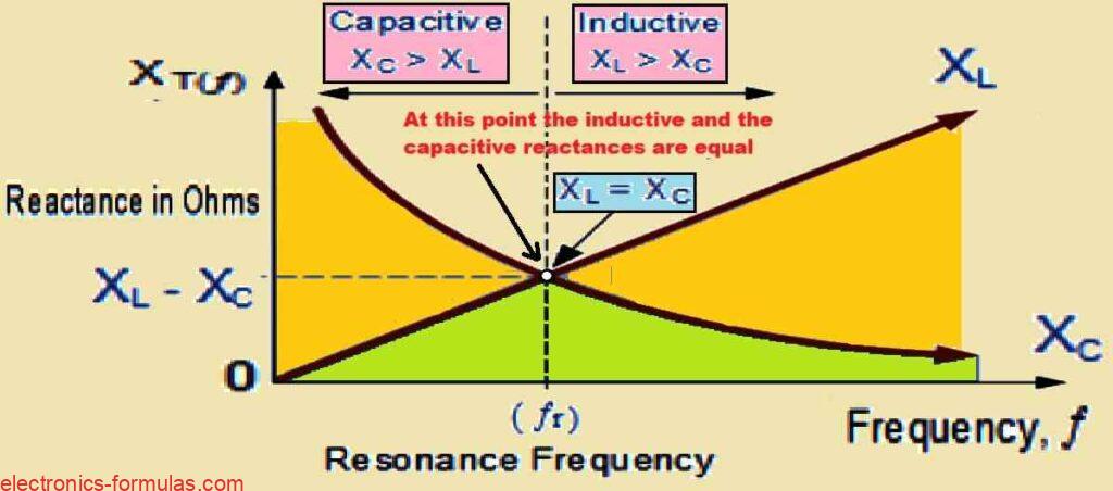
Formation Of Resonance Point
Between extremes, inductor and capacitor interaction makes tuned or resonant circuit. Resonant Frequency symbol (fr), inductive and capacitive reactances cancel.
Only resistor left opposing current. Voltage and current in phase, now look at circuit diagram, that is clear
Understanding Basic LC Oscillator Tank Circuit
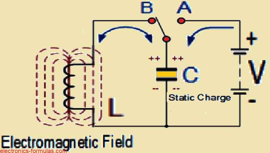
Basic Idea Of LC Tank Circuit
We can say this whole thing has mainly two big parts, one inductive coil L and one capacitor C.
So now, the job of capacitor is storing energy like electric field, makes some static voltage sitting across plates of C. But inductive coil L is storing energy like electromagnetic field around its turns.
Switch first goes to position A, we connect capacitor with DC supply V, let it slowly charge. Then after that, move switch to position B when capacitor fully charged, we complete next action of circuit.
Capacitor Discharging Into Inductor
Now capacitor carrying charge, and inductor L also connected in parallel, so capacitor starts pushing charge into coil. Current goes inside coil, begins increasing, and voltage across C slowly falls down.
Rising current builds electromagnetic field around coil, that field tries to oppose rapid change of current.
Now after capacitor C fully empty, all energy sitting as electrostatic field gets pushed into inductor L, sits there like electromagnetic field around winding.
Induced EMF And Reverse Charging
No external voltage in this loop, current in coil starts falling, electromagnetic field collapses. When field collapses, coil produces reverse emf e = −L (dt/di), and this keeps current moving in same old direction.
Because of induced emf, capacitor C starts charging again, but polarity totally opposite to first. Charging continues until electromagnetic field in coil zero, and current in coil also zero
Cycle Repeats
Circuit again receives back same energy injected earlier with switch, voltage on capacitor plates present again, opposite polarity. So cycle starts repeating, capacitor begins discharging through coil again
Energy keeps jumping back and forth between capacitor C and inductor L, polarity keeps flipping, we get AC type oscillation, looks like sinusoidal waveform for voltage and current.
LC Tank Working Principle
This repeated back-and-forth movement is basic working idea of LC tank inside LC oscillator. Energy keeps shifting from C to L and from L to C, in theory can keep happening forever.
But real life nothing perfect, every time energy moves from C to L then L to C, some loss happens, so oscillation slowly becomes smaller, finally zero.
Practical Losses In LC Circuit
In ideal imagination world, oscillation never stops but in real world many losses: coil resistance, dielectric loss of capacitor, small radiation, other minor resistances.
Losses slowly eat energy, amplitude reduces, until zero and stops.
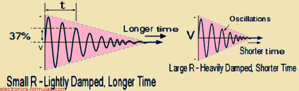
Damped Oscillation And Q-Factor
In practical LC circuit, oscillation becomes smaller each half cycle, finally almost dies down. We call this damped oscillation. Amount of damping depends on Q-factor. Low Q-factor means more loss, heavy damping. High Q-factor means less loss, damping very little.
What is Damped Oscillations
Deciding The Frequency Of LC Tank Circuit
We can say we are deciding frequency of oscillating voltage in LC tank circuit when we select inductance and capacitance correctly. We know tank circuit goes into resonance only at one exact frequency, and must remember that at this point inductive reactance XL and capacitive reactance XC become equal
So now, when XL equals XC, both cancel each other, and only DC resistance stays in circuit, that stops current from running wildly
Visualizing Resonance Curves
Now imagine we take curve of capacitive reactance of capacitor and curve of inductive reactance of inductor, put both on same frequency axis. Then we easily see one point where both curves touch each other. That point is resonance frequency fr or τr, and that point is very important, because it shows exact situation where LC tank circuit hits resonance condition
Understanding the Resonance Frequency
Resonant Frequency Basic Explanation
Now we look at that diagram above, and we see fr will be in Hertz, L in Henries, C in Farads.
We try to explain how this resonance happens, and we then say the frequency at which resonance will take place can be written like XL = 2πfL and XC = 1/2πfC.
When resonance happens, then at that exact moment XL = XC, and so we put both equal, we get 2πfL = 1/2πfC. Now move steps, write 2πf2L = 1/2πC, and then finally reach f2 = 1/(2π)2LC.
So we simplify more, f = √1/√[(2π)2LC], simple
Final Resonant Frequency Formula
So now we make everything simpler and get final equation for Resonant Frequency fr for any LC tuned circuit, that becomes
fr = 1/2π√LC.
L is Inductance in Henries, C is Capacitance in Farads, fr is Output Frequency in Hertz.
From this equation, we see if any one of L or C decreases, frequency goes high. Normally we use fr as short form, that tells us this is resonant frequency of LC system
Energy Restoration In LC Tank Circuit
We know in LC tank circuit, must keep oscillation alive, and we then understand we have to put back all energy lost during each cycle, and hold amplitude at some level.
That means energy put back must equal energy lost every cycle. LC tank must always restore lost energy and keep amplitude steady so oscillation does not stop
But now if energy replaced becomes too much, amplitude climbs until supply rails start clipping. And if restored energy too little, oscillation dies slowly, amplitude drops to zero.
Using Amplifier For Feedback Energy
So putting back lost energy is easy, just take some part of LC tank output, amplify it, feed back into LC circuit. We can use voltage amplifier with op-amp or FET or bipolar transistor as active device.
But we also remember, if loop gain of feedback amplifier too high, waveform gets distorted, and if loop gain too low, oscillation falls to zero, never sustains.
Need For Proper Gain Control
So total energy through feedback loop into LC network has to be precisely controlled, so continuous oscillation happens. If amplitude tries to go up or down from reference, then automatic amplitude control or automatic gain control may be needed in circuit
Unity Gain Requirement
So for stable oscillation, total gain of circuit must be exactly 1, or unity. If gain too low, oscillation never starts or slowly falls to zero. If gain too high, supply rails clip amplitude, create distortion. So now let us look at circuit shown below
Analyzing a Basic Transistorized LC Oscillator Circuit
Basic Working Of The LC Oscillator Using BJT
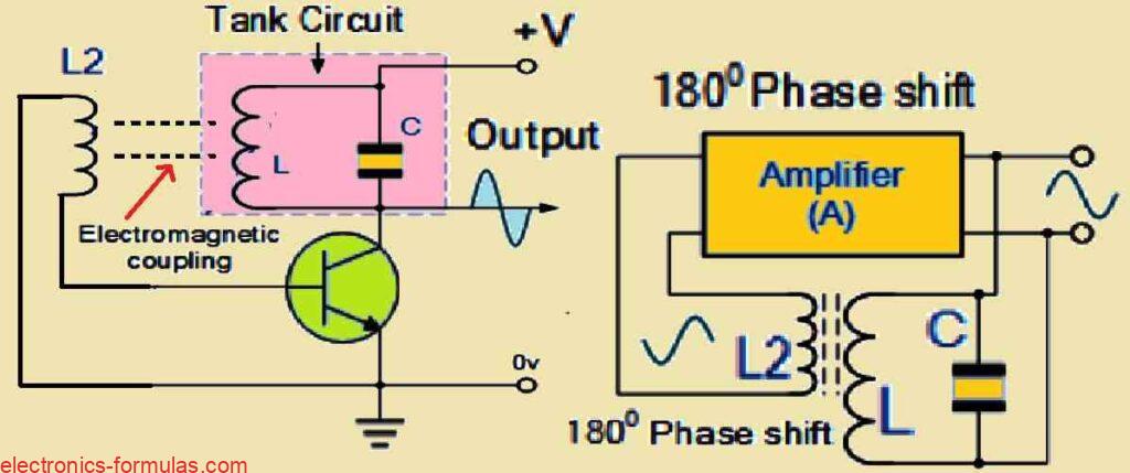
Now we look at the diagram, we see one Bipolar Transistor used like amplifier in LC oscillator. Tuned LC tank circuit acts like load for transistor.
You also see one extra coil called L2 connected between base and emitter of transistor. Electromagnetic field from coil L2 interacts strongly with field of coil L, so the two coils start working with mutual inductance between each other
Mutual inductance makes changing current in one coil produce voltage in other coil through electromagnetic induction.
Now when oscillations happen inside tuned circuit, energy moves from coil L to coil L2, this creates voltage at same frequency as oscillations. Then this voltage pushed back to transistor base, helps transistor amplify signal again and again.
Adjusting The Feedback Amount
Now feedback can be adjusted by changing distance between coils or making L and L2 more close or less close. When circuit oscillates, its impedance acts like resistor, voltages at collector and base stay 180 degrees out of phase.
For keeping oscillations going non stop, frequency stability process, important that tuned circuit voltage stays in-phase with oscillations.
Need For 180 Degree Additional Phase Shift
To make this possible, must introduce another 180 degree phase shift in feedback path from collector to base. Now winding direction of coil L2 must align with coil L, or sometimes we use some phase shift network between BJT amplifier output and input, simple.
Why This Is Called Harmonic Oscillator
Because of that phase shifting situation, we normally call this LC oscillator a Sinusoidal Oscillator, or sometimes Harmonic Oscillator.
These LC oscillators produce high frequency sine waves, normally used in radio frequency devices where amplifier section made using BJT or FET device.
Different Types Of Harmonic Oscillators
You will see many types of harmonic oscillators because many ways to build LC filter network and amplifier. Common examples are Hartley LC Oscillator, Colpitts LC Oscillator, Armstrong Oscillator, Clapp Oscillator.
Solving One LC Oscillator Example
So let us now take one inductance coil having inductance 150 mH and one capacitor having capacitance 25 pF. So these two components are connected in parallel and make one LC tank circuit and we want to find the oscillation frequency. So now we take the known values like L = 150 mH = 150 * 10-3 = 0.150 H and C = 25 pF = 25 * 10-12 F.
Our main frequency formula is f = 1 / (2π√LC).
First we solve LC which gives LC = 0.150 * 25 * 10-12 = 3.75 * 10-12.
So we solve √LC which becomes √(3.75 * 10-12) ≈ 0.00000193649.
We find 2π√LC which becomes 2π(0.00000193649) ≈ 0.00001216732.
We calculate f which is approximately 1/(0.00001216732) ≈ 82187.36 Hz.
So the final answer is almost f ≈ 82.18 kHz.
So now you can try and see that in the above calculations when you decrease the value of C or when you decrease the value of L then the final frequency of oscillation of the LC tank circuit will increase.
Conclusions
We see from all above that for keeping oscillations running and sustained, we must include reactive component in oscillator circuit, that reactive component must be either inductor L or capacitor C along with normal DC supply.
Now when you test one simple LC circuit then, oscillations get damped slowly because of internal component losses and total circuit losses. So because of that it becomes very important to include voltage amplification stage, so we can cancel those losses and make gain positive.
We also have to remember gain of amplifier must be slightly more than 1, which we also call unity.
For keeping continuous oscillation we must apply feedback signal which is just part of output voltage, and we feed this voltage back into tuned circuit.
So this feedback must have correct magnitude, and it must be exactly in-phase, 0 degrees with original waveform.
It is very important to remember that oscillations happen only when we apply positive feedback, which helps oscillations regenerate by themselves.
Lastly we must be careful about total phase shift of oscillator circuit, and ensure phase shift is 0 degrees or 360 degrees, because only then output signal from feedback network stays in-phase with input signal, and only then oscillation can continue in stable and effective manner.
References: LC circuit
good day
i need guide and support on induction heater coil circuit
thanks
Thank you, please give more details, I will try to help….