This circuit we seeing here, this one is not like old wax candle which use fire, paraffin or wax. Nothing like that here. Still it glows just like one real candle and looks like that also. But here we are using only some basic electronic parts like LED and battery, very simple ones. The cool part is we can even blow this candle off just like real one—just one small puff of air and it is gone!
Now this modern electronic LED candle circuit, it is meant for removing those boring old candles from our life which use real wax and burn and make mess and smell sometimes. This one is very clean.
This circuit, it gives more light than real candle and also it works for long time. Also it is cheap—no need to buy candles again and again.
And yeah making this circuit with our own hands at home is like one fun DIY thing.
What’s So Cool in This Circuit?
We got few awesome features in this candle circuit, like:
LED gives bright light.
Uses less power.
Turns ON automatically when light (AC) goes OFF.
And yeah like we said, we can blow it OFF just by mouth—just one puff or even small tap, and light goes out like real candle.
How This Thing Works (Circuit Operation)
WARNING – Very risky circuit! This one runs directly from AC mains. So if we touch it while working and it is connected to socket then it can give shock or even kill. So never touch on this circuit with power ON and without a covering. Be very careful!
Before we go inside the working, we must understand that this circuit has no isolation from mains AC. So it can carry full 220V AC live which is dangerous.
We must handle everything with big care while building or testing.
Now we will see how it works, step-by-step.
We can break this whole circuit into 3 main parts:
- Transformerless Power Supply Section
- LED Driving Section
- Puff Detection (Amplifier) Section
- Power Supply Part (No Transformer Used)
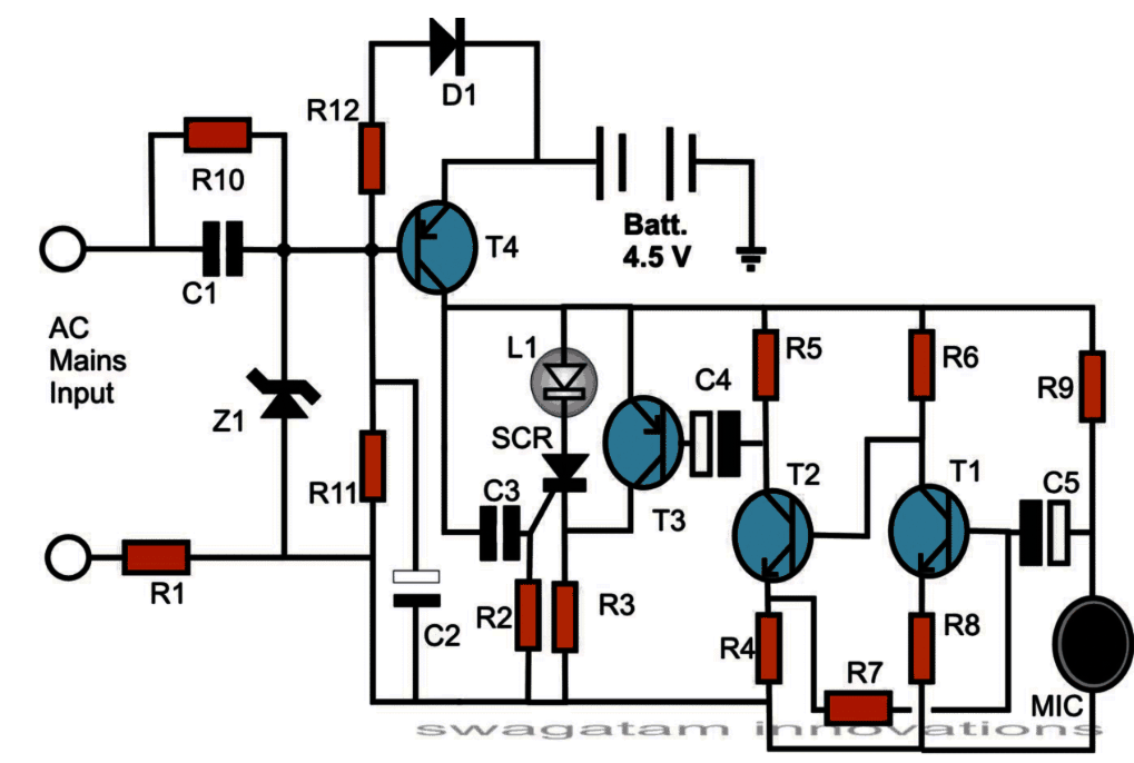
Now, the parts C1, R10, R1, Z1, all of them make one basic capacitive type power supply. This section mainly helps to make the circuit “understand” if AC mains is present or not. Also it makes sure the LED stays OFF when mains is ON.
AC mains comes in through R1 and C1.
R1 is here for safety, so when we first plug into socket, that sudden surge doesn’t burn anything. R1 blocks that rush current.
After that C1 gives the proper current to Z1 section.
Then the Zener diode (Z1) does the job of clamping.
For positive AC half cycle Z1 cuts the voltage to 12V max.
For negative cycle Z1 sends it straight to ground like short.
This helps again to stop surge and gives a smooth, safe voltage to the rest.
Then C2 filters that DC and makes it proper smooth DC for using.
Now what about R10 and T4?
R10 gives biasing to T4 transistor.
But when mains is present, then base of T4 becomes positive.
So any negative from ground cannot reach base.
That means T4 stays OFF.
And battery which is connected at emitter of T4 also stays cut off.
So now as long as mains power is present, the battery cannot give any power to LED part. So LED is OFF.
- What Happens When Mains Goes OFF?
If AC mains goes OFF then that positive at T4 base is gone.
Now R11 gives a path from ground to base of T4. So now T4 switches ON.
Now battery voltage can go from emitter to collector of T4.
This power reaches next stage and also goes through C3 for just one short moment.
That short moment of voltage from C3 is enough to trigger the SCR.
Now SCR turns ON and locks itself, even when C3 is fully charged and not giving anything.
This locked SCR allows full battery voltage to reach the LED and now LED glows.
So now as long as AC mains is OFF, this LED will remain glowing.
But when mains comes back again then T4 again gets switched OFF, battery gets disconnected, and LED also turns OFF.
- Now the Puff Part – How We Blow It OFF?
Now, the real candle feel comes here.
When AC power is not there and LED is glowing, we can switch it OFF just by puffing on it or tapping lightly.
This works with help of MIC (microphone).
MIC picks up small sound vibrations and gives very tiny electrical signals.
These signals go through T1, T2, and T3 they all are amplifiers.
After amplification T3 gets ON and it gives positive voltage to the anode of SCR.
This action removes the latching from SCR, and SCR goes OFF.
Once SCR is OFF, then LED also turns OFF.
So that is how this thing works like real candle.
Extra Feature – Charging the Battery
When mains is ON, then D1 diode gives small current to the battery.
So the battery gets charged slowly, like trickle charging.
How to Make This at Home?
We can use general method to build this, using veroboard (strip board). Just follow the schematic diagram.
To make it look like real candle:
Take one long plastic pipe, like candle shape.
Fix LED on top of pipe.
All circuit can go inside a small plastic box at bottom.
Attach pipe and box together.
Also fix two AC pins to the box so we can directly plug it into wall socket.
Battery goes inside pipe body. Use three 1.2V rechargeable pen cells in series to get total 4.5V.
Parts List
| Part | Value | Qty |
|---|---|---|
| R1, R3 | 47 Ohm, 1W | 2 |
| R4 | 1 K | 1 |
| R5 | 3.3 K | 1 |
| R2, R6 | 10 K | 2 |
| R7 | 47 K | 1 |
| R8, R12 | 150 Ohm | 2 |
| R9 | 2.2 K | 1 |
| R10 | 1 M | 1 |
| R11 | 4.7 K | 1 |
| C1 | 1 µF / 400V | 1 |
| C2 | 100 µF / 25V | 1 |
| C3 | 1 µF | 1 |
| C4, C5 | 22 µF / 25V | 2 |
| D1 | 1N4007 | 1 |
| T1, T2 | BC547 | 2 |
| T3, T4 | BC557 | 2 |
| SCR | 100V, 100 mA type | 1 |
| LED | White, 5mm High Bright | 1 |
| MIC | Electret MIC | 1 |
Leave a Reply