This article explains a few easy circuits that, when implemented, can stop single-phase problems in three-phase systems.
Overview
We are all aware that in order to operate big electrical loads effectively and sustainably, three phase electricity, or AC, is needed.
All three stages must, however, be present at all times for this to occur. The linked systems may suffer catastrophic effects if any of the steps fail. A straightforward yet efficient method for addressing the aforementioned issues is provided in the article that follows.
As was previously said, for a three-phase load, which includes an industrialized heavyweight motor, to operate correctly and dependably, each of the three input AC mains phases must be present.
Should there be any disparity in the input phases, the motor may begin to function under extremely stressful and unusual circumstances.
This may result in excessive current utilization, winding heating up, and eventually motor component burning.
How the Circuit Works
The single phasing preventor circuit listed below may be implemented to successfully eliminate any number of unwanted effects that could arise from an atypical three-phase problem.
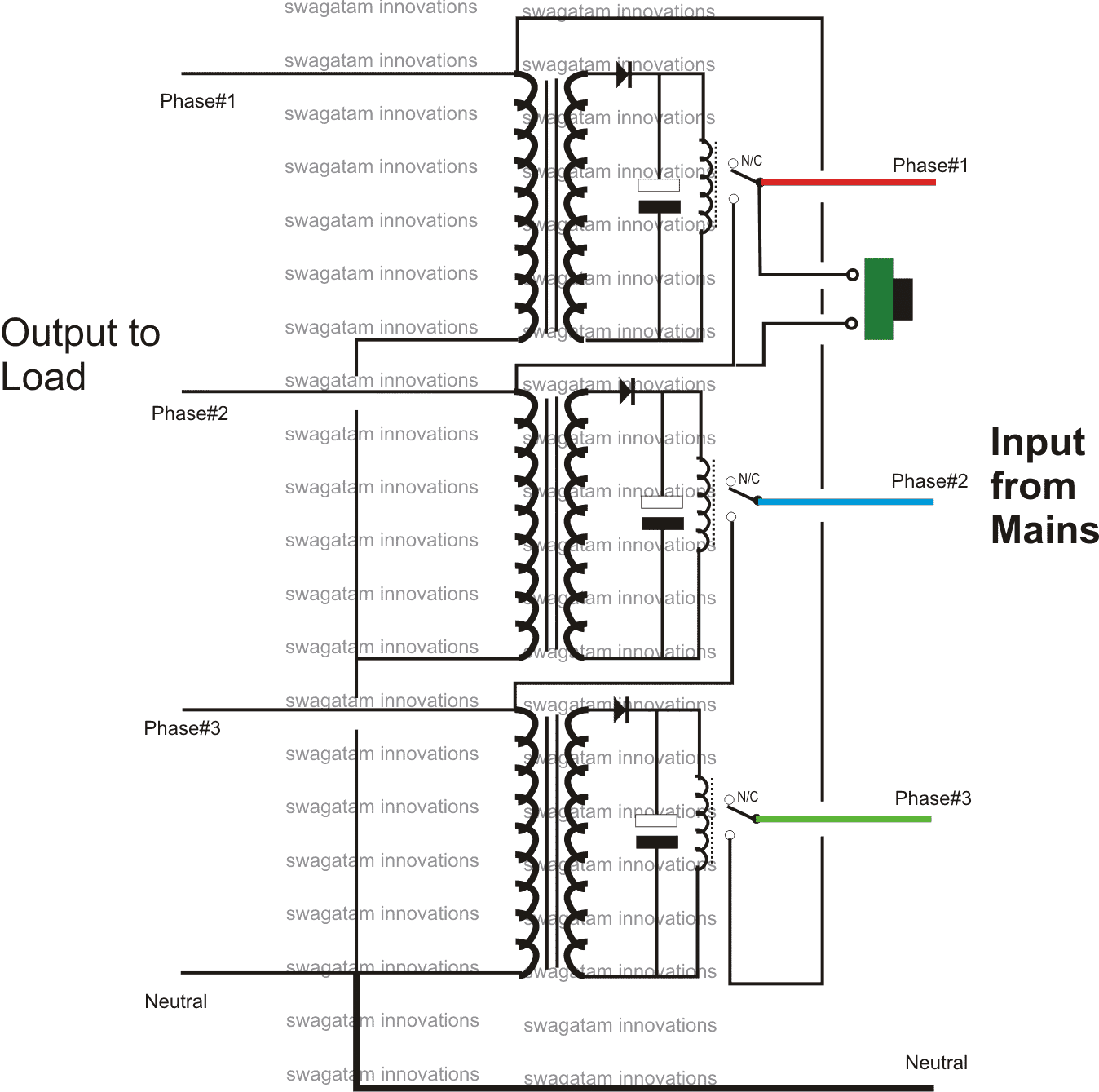
The utilization of three transformer/relay driver stages is shown in the schematic.
Transformers that are rated suitably for switching the attached relays might be the standard step-down varieties.
Every transformers have a common input main terminal that is linked to the neutral line.
Each transformer's remaining terminals are connected to the corresponding input mains' first, second, and third phases.
But in order to perform the necessary single phasing mitigation, the aforementioned connections are skillfully made via the relay N/O contacts of the successive relay assemblies.
Given that all of the relay contacts are open, the phases are first disconnected from the output load when the configuration is coupled with the three phases according to the specified interconnections.
The specific phase in the line is permitted to connect with the second or middle transformer primary winding upon pushing the designated push button.
The center transformer powers the corresponding relay instantaneously. Its connections, similar to those of the relay above, link the second phase to the bottom transformer's primary, which subsequently turn powers the foremost transformer.
Following this, the whole setup is latching through the relays' N/O contacts, ensuring that the outputs and transformers maintain their voltages regardless of whether the push button is withdrawn.
Assume that the output loads are immediately stopped and disconnected if any of the phases fail or become low. The specific transformer in line would then straight away disconnect its relay, and the entire relay system would then malfunction sequentially.
As a result, the system successfully stops the loads from running when any phase is absent, ensuring that no fumes are released.
I assume that I created the circuit entirely; if it has previously been found, please send me with the URL:
Leave a Reply