• Skip to main content
  • Skip to primary sidebar

Making Easy Circuits

Learn and build electronic circuits

You are here: Home / Audio and Amplifier / Mouth Operated Music Synthesizer Circuit

Mouth Operated Music Synthesizer Circuit

Last Updated on April 10, 2020 by Admin Leave a Comment

In this article we discuss a simple circuit which can used to synthesize music by blowing a MIC with breath power from mouth.

The air pressure and vibration generated by the breath on the MIC will create musical effects at the output which can be amplified for further processing.

How it Works

Usually the key switches control the circuits that generate electronic music.

Keyboards not just provide the simplest technical solution for producing fast changing and reproducible tones with a vast range of frequency, but they also have significant popularity because they are counted as an easier instrument to learn than that of musical instruments with string or wind.

Due to that, we haven’t took the initiative to create an electronic oboe, flute or clarinet with the existing circuit.

The technical complexities associated with such instruments would make their electrophonic counterpart considerably expensive.

To avoid that, a relatively simple facility of converting breath to power into a proportional analogue voltage is being presented here.

With the voltage the volume of the music synthesizer can be controlled.

The tones can be controlled by the switches of the keyboard. Undoubtedly, many readers are already thinking of various other application of this converter.

blow synthesizer

Circuit Description

The mouth operated synthesizer circuit doesn’t operate directly from the breath the user exhaled, rather from the noise generated by this. A thin and flexible tube is being used.

The mouthpiece , may be attached to this – it leads into a closed box. Inside the closed box there are the circuit, as well as an inexpensive microphone is fitted – the structure is depicted in the diagram.

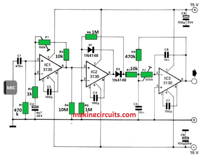
The noise that the microphone receives, gets amplified in IC1, this gain can be adjusted with P1 and the noise can be subsequently corrected by IC2-D1-D2.

Most of the ripples from the output voltage is removed by an active low-pass filter.

The designers have chosen for a compromise between input sensitivity and output ripple, to keep the circuit as simple as it could be.

If the user has an oscilloscope having slow sweep, calibration of the converter won’t be problematic.

First one needs to adjust the value of P1, so that the output voltage with hard blowing into the tube is not being able to cause full-drive.

However, this is depending on the sensitivity of the following instrument.

Secondly, the user needs to adjust P2, so that the output signal is comparatively free of ripples.

At the same time, the converter still reacts if someone breaths normally. A steeper filter must had improved the accessory, however, that would be a bit more costly.

You'll also like:

  • 1.  How to Make a Cellphone RF Triggered Car Amplifier Auto-Mute Circuit
  • 2.  Convert Whistle Sound to Electronic Music
  • 3.  Theremin Circuit
  • 4.  Dynamic MIC Preamplifier Circuit
  • 5.  Simple Bird Sound Generator Circuit
  • 6.  Anti-Acoustic Feedback Circuit For Microphone/Amplifier Systems

About Admin

Hey friends, Thanks a bunch for stopping by this site! I am an engineer with a Bachelor of Engineering in Electronics and Telecommunication. One of my passions is gathering information from all sorts of electronics books and tutorials. I then take that information and compile it into a language that is super easy to understand. My goal is to make those complex electronics circuit concepts and technical terms much more accessible for all the new and budding electronics engineers out there. I can also design customized circuit diagrams as required by the users.
If you have any questions related to this field, please do not hesitate to drop a comment! I am always here and ready to help you out with any queries you might have. I cannot wait to hear from you!

Reader Interactions

Leave a Reply Cancel reply

Your email address will not be published. Required fields are marked *

Primary Sidebar

Categories

  • 3 Phase (4)
  • 8051 Microcontroller (1)
  • Arduino (11)
  • Audio and Amplifier (102)
  • Automation (8)
  • Battery Chargers (64)
  • Bicycle Projects (4)
  • Car and Motorcycle Projects (39)
  • Datasheets (10)
  • DIY Projects (5)
  • Electrical (15)
  • Free Energy (6)
  • Games Projects (2)
  • High Voltage (14)
  • Hobby Projects (30)
  • Household Circuits (2)
  • IC 555 Circuits (5)
  • Ignition Circuits (2)
  • Indicators (50)
  • Infrared (6)
  • Inverter Circuits (29)
  • Lights and Lamps (97)
  • Medical (8)
  • Meter and Tester Circuits (38)
  • Motor Driver (17)
  • New Circuits (56)
  • Oscillators (30)
  • Pets and Pests (5)
  • Power supply (80)
  • Protection Circuits (25)
  • PWM (9)
  • Remote Control (20)
  • Security and Alarm Circuit (48)
  • Sensors and Detectors (66)
  • Signal Processor (23)
  • Solar Controller Circuits (62)
  • SSR (3)
  • Temperature Controller (20)
  • Timer (25)
  • Transformerless (7)
  • Transmitters (12)
  • Tutorials (45)
  • UPS (2)
  • Voltage Regulators (57)
  • Water Sensor and Controller (29)
  • Home
  • Privacy Policy
  • Contact
  • Disclaimer
  • Copyright

© 2025 · Making Easy Circuits