• Skip to main content
  • Skip to primary sidebar

Making Easy Circuits

Learn and build electronic circuits

You are here: Home / Hobby Projects / Push-Button ON/OFF Switch using Schmitt Trigger

Push-Button ON/OFF Switch using Schmitt Trigger

Last Updated on January 10, 2018 by Admin Leave a Comment

A pretty helpful functionality expressed in a simple push-button ON/OFF switch using schmitt trigger circuit that may be well suited for several applications. Basically the output of the Schmitt trigger N1 changes (toggles) as soon as the switch is closed briefly.

This single push button toggle ON/OFF function is accomplished in such a straightforward circuit from the simple fact that the inputs of the trigger are performed in between the switching threshold ranges. if we assume that the output logic level (Q) of the trigger reaches logic 1, capacitor C1 will charge through R1.

If switch S1 is closed the input of the trigger will now automatically get to logic 1 (since the capacitor is completely charged) and also the Q output may naturally turn into reasoning '0'.

The capacitor C1 will at this point discharge however, not entirely as the closed switch will probably retain the level to that prevailing at the wiper of P1.

024

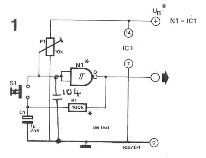
On the other hand this drop in voltage on the input of the gate is not going to trigger its output to alter state yet again since the input level will still be over a lower switching limit of the Schmitt trigger. This ‘intermediate’ voltage level will continue while the switch is pressed.

Once the switch is at some point released, C1 will subsequently discharge totally. The 0V over the capacitor will never impact the trigger because it is no longer attached to the capacitor (the switch is open).

At this point once the switch is closed the 0V may achieve the input of the gate and its output may yet again change state. It is crucial that P1 is defined accurately for the circuit to function however it will be discovered in practice this presents no issue. Different types of Schmitt trigger suit this circuit: 4093, 40106, 74LS14, 74LS132. If TTL lCs are employed, the supply voltage should be 5 V; for CMOS lCs it may lie in between 5 V and 15V.

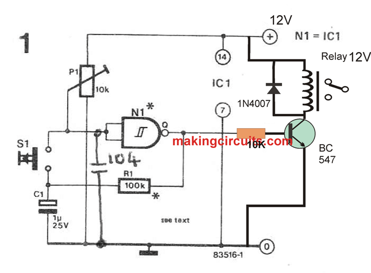
The above discussed push-button electronic ON/OFF switch circuit can be integrated with a relay or triac to operate any type of heavy load by simply toggling the push-button ON/OFF.

push

You'll also like:

  • 1.  Keyboard Beep Circuit
  • 2.  Horse Pace Sound Simulator Circuit
  • 3.  Simple Latch Circuit using Transistors
  • 4.  Sea Surf Sound Effect Simulator Circuit
  • 5.  12 Simple NAND Gate Hobby Circuits – Schmitt Trigger Circuits
  • 6.  Simple SCR Circuits

About Admin

Hey friends, Thanks a bunch for stopping by this site! I am an engineer with a Bachelor of Engineering in Electronics and Telecommunication. One of my passions is gathering information from all sorts of electronics books and tutorials. I then take that information and compile it into a language that is super easy to understand. My goal is to make those complex electronics circuit concepts and technical terms much more accessible for all the new and budding electronics engineers out there. I can also design customized circuit diagrams as required by the users.
If you have any questions related to this field, please do not hesitate to drop a comment! I am always here and ready to help you out with any queries you might have. I cannot wait to hear from you!

Reader Interactions

Leave a Reply Cancel reply

Your email address will not be published. Required fields are marked *

Primary Sidebar

Categories

  • 3 Phase (4)
  • 8051 Microcontroller (1)
  • Arduino (11)
  • Audio and Amplifier (102)
  • Automation (8)
  • Battery Chargers (64)
  • Bicycle Projects (4)
  • Car and Motorcycle Projects (39)
  • Datasheets (10)
  • DIY Projects (5)
  • Electrical (15)
  • Free Energy (6)
  • Games Projects (2)
  • High Voltage (14)
  • Hobby Projects (30)
  • Household Circuits (2)
  • IC 555 Circuits (5)
  • Ignition Circuits (2)
  • Indicators (50)
  • Infrared (6)
  • Inverter Circuits (29)
  • Lights and Lamps (97)
  • Medical (8)
  • Meter and Tester Circuits (38)
  • Motor Driver (17)
  • New Circuits (56)
  • Oscillators (30)
  • Pets and Pests (5)
  • Power supply (80)
  • Protection Circuits (25)
  • PWM (9)
  • Remote Control (20)
  • Security and Alarm Circuit (48)
  • Sensors and Detectors (66)
  • Signal Processor (23)
  • Solar Controller Circuits (62)
  • SSR (3)
  • Temperature Controller (20)
  • Timer (25)
  • Transformerless (7)
  • Transmitters (12)
  • Tutorials (45)
  • UPS (2)
  • Voltage Regulators (57)
  • Water Sensor and Controller (29)
  • Home
  • Privacy Policy
  • Contact
  • Disclaimer
  • Copyright

© 2025 · Making Easy Circuits