• Skip to main content
  • Skip to primary sidebar

Making Easy Circuits

Learn and build electronic circuits

You are here: Home / Indicators / Road Diversion Warning Indicator using Running LED Lights

Road Diversion Warning Indicator using Running LED Lights

Last Updated on January 10, 2018 by Admin Leave a Comment

The discussed LED lamp chaser circuit can be effectively used for indicating or warning road diversions or when a roadwork is in progress, especially in areas where street lamps are absent and in accident prone dark roadways.

Roadworks and highways are usually marked during the hours of darkness by yellow flashing lights. These may often be linked together to form a ‘running’ flashing light.

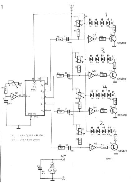
Road diversions and the like are then clearly visible. The road diversion warning indicator circuit using running LED lights described here provides a similar effect but for use in model roadways for instance. The speed of the ‘running’ row of LEDs is determined by the frequency of the clock generator N1.

Depending on the type of lC used, this frequency will be of the order of 6 Hz 1 30% when potentiometer Pl is in mid position. The output of the clock generator is fed to the Johnson counter lC1L The outputs of this counter become logic 1 in sequence.

The counter is reset to the start when Q4 goes to logic 1. This explains the link between pins 15and 1001‘ lC1.0utputs Q0. . . Q3 are connected to four monostable multivibrator circuits consisting of N2 . . . N5.

The multivibrators are triggered by the negative going edge of the square wave outputs of Q0 . . . Q3 and the pulse period can be preset with potentiometers P2 . . . P5 which of course determine how long each group of LEDs will light. These periods need to be more or less equal to ensure smooth running of the lights. The circuit uses four groups of four LEDs each.

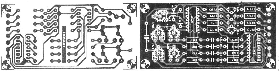
The LEDs in each group will light simultaneously. Figure 2 shows how the LEDs should be connected for road markings in a bend: LEDs D16, D15, D14 and D13 light first, followed by D12, D11, D10  and D9, and so on.  Schmitt triggers N2 . . . N5 are not  capable of supplying sufficient current for the LE Ds and therefore the  buffers T1 . . . T4 are included. The  current through the LEDs is about  30 mA during each flash;the average  current taken by the circuit operating  at the highest frequency is of the  order of 30 mA. When, however, the  flash period is longer than the  running period, the current consumption may rise to a maximum of  100 mA.  The printed circuit board (see  figure 3) is fairly compact. The  preset potentiometers are neatly  grouped together and all terminals  are located at one edge. The four  groups of LEDs are connected to  pins A . . . D which are clearly marked  on the circuit diagram and the board.

Parts list for the proposed road diversion warning indicator circuit using running LED lights
Resistors:
R1 =47k
R2...R5,R10...R13=10k
R6..'.R9=22k
R14...R17=47S2.
P1 . . . P5 = 1 M preset potentiometer
Capacitors:
C1 =330n
C2...C5=100n
C6=10;u/16V
Semi-conductors:
' T1 ...T4=BC547B
D1 . . . D16 = LED yellow
IC1=4017
IC2 =40106

road diversion warning indicator circuit using running LED lights


006

You'll also like:

  • 1.  Automatic Light Circuit for Washroom  
  • 2.  Simple 5 LED Music Level Indicator using a single IC
  • 3.  20 watt, 5 watt Fluorescent Lamp Inverter Circuit
  • 4.  Test Logic with this Logic Probe Circuit
  • 5.  3 LED Battery Monitor Circuit
  • 6.  Mains AC Voltage Monitor Circuit

About Admin

Hey friends, Thanks a bunch for stopping by this site! I am an engineer with a Bachelor of Engineering in Electronics and Telecommunication. One of my passions is gathering information from all sorts of electronics books and tutorials. I then take that information and compile it into a language that is super easy to understand. My goal is to make those complex electronics circuit concepts and technical terms much more accessible for all the new and budding electronics engineers out there. I can also design customized circuit diagrams as required by the users.
If you have any questions related to this field, please do not hesitate to drop a comment! I am always here and ready to help you out with any queries you might have. I cannot wait to hear from you!

Reader Interactions

Leave a Reply Cancel reply

Your email address will not be published. Required fields are marked *

Primary Sidebar

Categories

  • 3 Phase (4)
  • 8051 Microcontroller (1)
  • Arduino (11)
  • Audio and Amplifier (102)
  • Automation (8)
  • Battery Chargers (64)
  • Bicycle Projects (4)
  • Car and Motorcycle Projects (39)
  • Datasheets (10)
  • DIY Projects (5)
  • Electrical (15)
  • Free Energy (6)
  • Games Projects (2)
  • High Voltage (14)
  • Hobby Projects (30)
  • Household Circuits (2)
  • IC 555 Circuits (4)
  • Ignition Circuits (2)
  • Indicators (50)
  • Infrared (6)
  • Inverter Circuits (29)
  • Lights and Lamps (97)
  • Medical (8)
  • Meter and Tester Circuits (38)
  • Motor Driver (17)
  • New Circuits (56)
  • Oscillators (30)
  • Pets and Pests (5)
  • Power supply (81)
  • Protection Circuits (25)
  • PWM (8)
  • Remote Control (20)
  • Security and Alarm Circuit (48)
  • Sensors and Detectors (66)
  • Signal Processor (23)
  • Solar Controller Circuits (61)
  • SSR (3)
  • Temperature Controller (20)
  • Timer (25)
  • Transformerless (7)
  • Transmitters (12)
  • Tutorials (45)
  • UPS (2)
  • Voltage Regulators (57)
  • Water Sensor and Controller (29)
  • Home
  • Privacy Policy
  • Contact
  • Disclaimer
  • Copyright

© 2025 · Making Easy Circuits