• Skip to main content
  • Skip to primary sidebar

Making Easy Circuits

Learn and build electronic circuits

You are here: Home / Audio and Amplifier / Sea Surf Sound Effect Simulator Circuit

Sea Surf Sound Effect Simulator Circuit

Last Updated on April 25, 2018 by Admin Leave a Comment

In this post we learn how to make a simple sea surf sound effect generator circuit  the sound simulation of true sea wave noise, and will give you a feel of sea shore in your home.

Overview

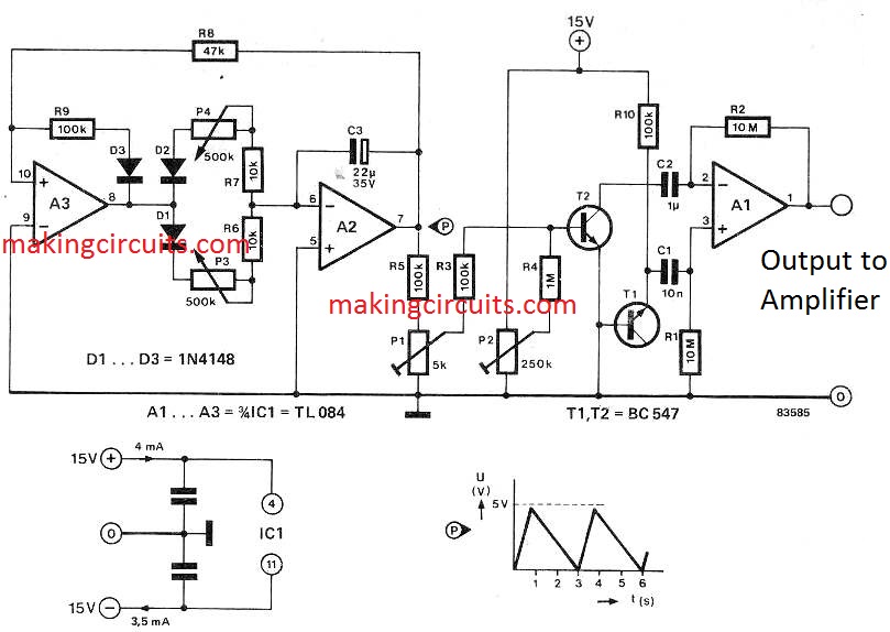
The heart of the circuit is the ‘murmuring source’ comprising T1 and R10. This constitutes an effect that is amplified in voltage controlled amplifier A1 as well as the subsequent external AF amplifier. Transistor T2 is employed like a current- controlled resistance that regulates the amplification of A1: the smaller the resistance, the more powerful the output signal.

The volume of the surf furthermore is determined by the output of the triangular pulse generator which involves integrator A2 and trigger A3. The output of the trigger is attached to the input of the integrator. Diode D3 is incorporated to avoid the output signal of A3 heading negative.

This really is essential or else the bottom portions of the triangular waveform coming from T1 might subsequently be cut-off and instead of a consistently growing and perishing down of surf you would probably get only disrupted breakers. The slopes of the triangular signal can easily be tweaked through potentiometers P3 and P4.

sea wave surf simulator sound effect circuit

Circuit Description

Diodes D1 and D2 enable the positive and negative slopes to become fine-tuned independent of each other. The potentiometers additionally figure out the frequency: the smaller sized their total value, the larger the frequency.

The proportion of the 2 potentiometers ascertains the balance of the signal. Throughout the calibration of the circuit, hook up the wiper of P1 to earth and after that fine-tune P2 for a smooth murmur within the loudspeaker. lf P2 is popped further, the volume level ought to boost. The background ‘whispering’ of the sea has become fixed now. Detach the wiper of P1 from earth and change the setting up of the potentiometer.

The tone of the breakers must subsequently improve and perish down at the frequency of the oscillator. Next fine-tune P2 right up until probable clipping is eliminated. Be aware that P1 and P2 impact one another to ensure that additionally fine manipulations might be required. At this point the ‘shape’ of the waves may be altered using P3 and P4. Tests have demostrated that a sea wave typically endures a few seconds through crest to crest.

The surge is generally 5to 10x smaller compared to fall and the necessary wave appearance is consequently much more a sawtooth than the usual triangle. Setting up P3 to around 470k and P4 to approximately 100k provides a incredibly reasonable sea surf sound effect simulation. These elements are adjustable since this makes it possible for the circuit specifically for other purposes, as an example, like a steam locomotive simulator, and likewise

You'll also like:

  • 1.  Fading Red Eye Circuit
  • 2.  Simple 20 watt Amplifier Circuit
  • 3.  How to Make an Opamp with Transistors (BJTs)
  • 4.  How to Make a Simple Musical Greeting Card
  • 5.  Music Light Circuit without Contact
  • 6.  Musical Doorbell Circuit with Many Melodies – Christmas Carols, Big Ben, and More

About Admin

Hey friends, Thanks a bunch for stopping by this site! I am an engineer with a Bachelor of Engineering in Electronics and Telecommunication. One of my passions is gathering information from all sorts of electronics books and tutorials. I then take that information and compile it into a language that is super easy to understand. My goal is to make those complex electronics circuit concepts and technical terms much more accessible for all the new and budding electronics engineers out there. I can also design customized circuit diagrams as required by the users.
If you have any questions related to this field, please do not hesitate to drop a comment! I am always here and ready to help you out with any queries you might have. I cannot wait to hear from you!

Reader Interactions

Leave a Reply Cancel reply

Your email address will not be published. Required fields are marked *

Primary Sidebar

Categories

  • 3 Phase (4)
  • 8051 Microcontroller (1)
  • Arduino (11)
  • Audio and Amplifier (102)
  • Automation (8)
  • Battery Chargers (64)
  • Bicycle Projects (4)
  • Car and Motorcycle Projects (39)
  • Datasheets (10)
  • DIY Projects (5)
  • Electrical (15)
  • Free Energy (6)
  • Games Projects (2)
  • High Voltage (14)
  • Hobby Projects (30)
  • Household Circuits (2)
  • IC 555 Circuits (5)
  • Ignition Circuits (2)
  • Indicators (50)
  • Infrared (6)
  • Inverter Circuits (29)
  • Lights and Lamps (97)
  • Medical (8)
  • Meter and Tester Circuits (38)
  • Motor Driver (17)
  • New Circuits (56)
  • Oscillators (30)
  • Pets and Pests (5)
  • Power supply (80)
  • Protection Circuits (25)
  • PWM (9)
  • Remote Control (20)
  • Security and Alarm Circuit (48)
  • Sensors and Detectors (66)
  • Signal Processor (23)
  • Solar Controller Circuits (62)
  • SSR (3)
  • Temperature Controller (20)
  • Timer (25)
  • Transformerless (7)
  • Transmitters (12)
  • Tutorials (45)
  • UPS (2)
  • Voltage Regulators (57)
  • Water Sensor and Controller (29)
  • Home
  • Privacy Policy
  • Contact
  • Disclaimer
  • Copyright

© 2025 · Making Easy Circuits