• Skip to main content
  • Skip to primary sidebar

Making Easy Circuits

Learn and build electronic circuits

You are here: Home / Battery Chargers / Self Regulating Battery Charger Circuit

Self Regulating Battery Charger Circuit

Last Updated on April 2, 2020 by Admin 2 Comments

Lead-acid batteries that remain unused for a long time will inevitably go bad. The self regulating battery charger circuit explained below is meant to keep such a battery healthy through the period of dormancy.

The circuit charges the battery and then allows it to discharge through itself as well as the internal resistance of the battery. Once the charge sinks below a certain level, the circuit once again charges it, thus continuing the cycle.

battery firness center

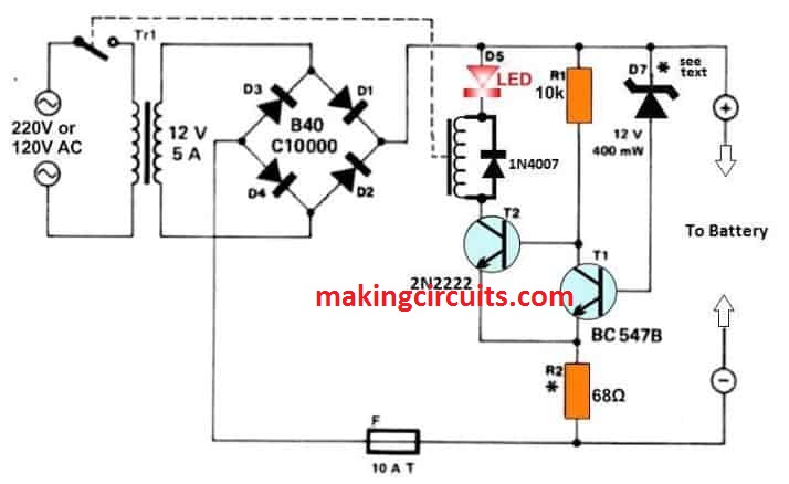
How the Circuit Works

The circuit works on a Schmitt trigger T1/T2. The charge at which the charger needs to switch off depends on the D7 Zener diode, while the necessary hysteresis is supplied by the R2 resistor.

Test the circuit by applying voltages of 13.6 V and 12.5 V across the battery terminals without the mains or any battery connected to it. The relay should switch off and on respectively.

The critical value for switching the charger on may be fixed by connecting a 1N4148 (cathode to + line) to D7 in series. The value for the off state can also be changed by varying R2, say by putting in a fixed 100 Ω resistance in its place.

Another possibility is using a battery charger in place of the bridge rectifier and the mains transformer, retaining the rest of the circuit and connecting it with the charger.

Keep in mind that the circuit will not work with a fully discharged battery - it must at least be charged to over 10 V. An alternative is to switch on the mains using a switch connected in parallel to the relay contact.

How to Charge two Batteries in Series

You can also maintain two 12 V batteries this way through automatic self regulation of their charging voltage, so that none of them over charges.

For this all you have to do is to raise the mains transformer secondary voltage, the D7 zener voltage, the voltage of the ralay coil and the hysteresis.

The circuit is completed by fitting both batteries across the terminals in series.

The circuit is protected against short circuits using the fuse F1. The same can be done for the transformer primary circuit using a delayed action fuse like F1 with a threshold of 1 A.

A smoothing capacitor is redundant here as the battery itself does that job.

You'll also like:

  • 1.  6V, 12V, 24V Battery Charger for Automobile
  • 2.  NiCd Fast Charger Circuit
  • 3.  Simple PWM MPPT Circuit using IC 555
  • 4.  Simple Solar Ni-Cd Charger Circuit
  • 5.  MPPT Solar Charger with 3-Step Charger Circuit
  • 6.  Fast Lead Acid Battery Charger Circuit

About Admin

Hey friends, Thanks a bunch for stopping by this site! I am an engineer with a Bachelor of Engineering in Electronics and Telecommunication. One of my passions is gathering information from all sorts of electronics books and tutorials. I then take that information and compile it into a language that is super easy to understand. My goal is to make those complex electronics circuit concepts and technical terms much more accessible for all the new and budding electronics engineers out there. I can also design customized circuit diagrams as required by the users.
If you have any questions related to this field, please do not hesitate to drop a comment! I am always here and ready to help you out with any queries you might have. I cannot wait to hear from you!

Reader Interactions

Comments

  1. Daniel Abbey says

    June 9, 2021 at 10:52 pm

    Good evening sir. Please I was reading about the self regulating battery charger. I don’t know much about electronics. How do I modify it to charge two 12 volts in series. The Ah is 200 each.
    Thank you. Please reply with the circuit diagram. My email address is: [email protected]

    Reply
    • admin says

      June 10, 2021 at 9:38 am

      Daniel, you can add two 12V in series, by modifying the zener diode accordingly by using a 25V zener, the relay will also need to be modified and replaced with a 24V relay. Needless to say the transformer will also need to be replaced with a 24V transformer. 68 ohms can be increased to 100 ohms

      Reply

Leave a Reply Cancel reply

Your email address will not be published. Required fields are marked *

Primary Sidebar

Categories

  • 3 Phase (4)
  • 8051 Microcontroller (1)
  • Arduino (11)
  • Audio and Amplifier (102)
  • Automation (8)
  • Battery Chargers (64)
  • Bicycle Projects (4)
  • Car and Motorcycle Projects (39)
  • Datasheets (10)
  • DIY Projects (5)
  • Electrical (15)
  • Free Energy (6)
  • Games Projects (2)
  • High Voltage (14)
  • Hobby Projects (30)
  • Household Circuits (2)
  • IC 555 Circuits (4)
  • Ignition Circuits (2)
  • Indicators (50)
  • Infrared (6)
  • Inverter Circuits (29)
  • Lights and Lamps (97)
  • Medical (8)
  • Meter and Tester Circuits (38)
  • Motor Driver (17)
  • New Circuits (56)
  • Oscillators (30)
  • Pets and Pests (5)
  • Power supply (81)
  • Protection Circuits (25)
  • PWM (8)
  • Remote Control (20)
  • Security and Alarm Circuit (48)
  • Sensors and Detectors (66)
  • Signal Processor (23)
  • Solar Controller Circuits (61)
  • SSR (3)
  • Temperature Controller (20)
  • Timer (25)
  • Transformerless (7)
  • Transmitters (12)
  • Tutorials (45)
  • UPS (2)
  • Voltage Regulators (57)
  • Water Sensor and Controller (29)
  • Home
  • Privacy Policy
  • Contact
  • Disclaimer
  • Copyright

© 2025 · Making Easy Circuits