• Skip to main content
  • Skip to primary sidebar

Making Easy Circuits

Learn and build electronic circuits

You are here: Home / Protection Circuits / Simple 220V Over and Under Voltage Protection Circuit

Simple 220V Over and Under Voltage Protection Circuit

Last Updated on November 25, 2018 by Admin 8 Comments

This very simple two transistor circuit will ensure that your home electrical and appliances are never affected by abnormal voltage fluctuations. This circuit designed to cut off the 220V supply whenever an over voltage or under voltage situation is detected. Thus all your home sensitive devices and gadgets are full protected from an voltage hazard situation.

How much will this unit cost? Probably not more than a dollar.

In many countries sudden ups and downs in the mains voltage is quite common, and sometimes this may cause a permanent failure of the many costly electrical gadgets such TCV sets, refrigerator LED lamps which are not designed to tolerate high voltages over a certain limit.

The circuit explained here, when correctly set will offer a safe voltage operating zone as preferred by the user, and if the voltage tends to exceed beyond or fall below this limit, the relay will trip cutting off power to the appliance thereby safeguarding it from the expected dangers.

220V over and under voltage protection circuit using transistors

The proposed design is simple, easy to construct and inexpensive. It can be added to existing stabilizer units in which case the DC power supply can be extracted from the stabilizer circuit and only a few additional components including relay would be required to build the circuit.

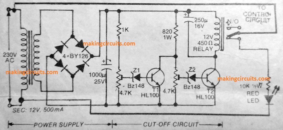
How the Circuit Works

When the 220V or 120V mains supply is within the set limits, T2 will be conducting, rendering T1 in a non-conducting state.

When voltage is lower than the set limit, zener Z2 will not breakdown and therefore T2 cannot conduct, when results in deactivation of the relay.
This adjustment is done by setting up VR2.

During an over voltage condition, zener Z1 will breakdown and T1 will get into a conducting state, de-energizing the relay. This setting is done by adjusting VR1.

Here, the relay's "normally-Open" contact is used for controlling the appliance's voltage supply. When N/O contact is connected the appliance is able to get normal voltage supply, while during an abnormal voltage condition the N/O is cut off, prohibiting the supply to the appliance.

The LED attached across the N/C contact of the relay informs us about the cut off situation and also regarding the under or over voltage protection switched ON.

You'll also like:

  • 1.  Simple Time Delay Relay Protector Circuit for Refrigerators
  • 2.  Simple Code Lock Circuit
  • 3.  Gas Sensor Circuit
  • 4.  Simple Mains Voltage Stabilizer Circuit
  • 5.  What is the Use of MOSFET Body Diode
  • 6.  Snubber Circuits for Protecting Relay Contacts from Arcing

About Admin

Hey friends, Thanks a bunch for stopping by this site! I am an engineer with a Bachelor of Engineering in Electronics and Telecommunication. One of my passions is gathering information from all sorts of electronics books and tutorials. I then take that information and compile it into a language that is super easy to understand. My goal is to make those complex electronics circuit concepts and technical terms much more accessible for all the new and budding electronics engineers out there. I can also design customized circuit diagrams as required by the users.
If you have any questions related to this field, please do not hesitate to drop a comment! I am always here and ready to help you out with any queries you might have. I cannot wait to hear from you!

Reader Interactions

Comments

  1. Ranesh Aponso says

    March 5, 2022 at 11:31 am

    How to set VR 1 & VR 2 to 180V to 250V, is there is a way of identifying. Please explain

    Reply
    • admin says

      March 20, 2022 at 7:27 am

      You will have to find out which DC voltage from the transformer corresponds to 180v and 250v, and then adjust the presets accordingly….

      Reply
  2. Ananda. says

    June 11, 2021 at 11:34 am

    Vary good circuits. Valuable.

    Reply
    • admin says

      June 16, 2021 at 7:03 pm

      thank you!

      Reply
  3. Agus says

    June 1, 2020 at 9:32 am

    whether this scheme works. I try it can’t work

    Reply
    • admin says

      June 3, 2020 at 5:33 pm

      yes it works

      Reply
  4. Anoop C P says

    December 18, 2019 at 8:03 pm

    Sir,
    Please sugest a equivalent zener diode for Bz 148.

    Reply
    • admin says

      January 1, 2020 at 12:36 pm

      Any value from 3 to 6V zener will do….

      Reply

Leave a Reply Cancel reply

Your email address will not be published. Required fields are marked *

Primary Sidebar

Categories

  • 3 Phase (4)
  • 8051 Microcontroller (1)
  • Arduino (11)
  • Audio and Amplifier (102)
  • Automation (8)
  • Battery Chargers (64)
  • Bicycle Projects (4)
  • Car and Motorcycle Projects (39)
  • Datasheets (10)
  • DIY Projects (5)
  • Electrical (15)
  • Free Energy (6)
  • Games Projects (2)
  • High Voltage (14)
  • Hobby Projects (30)
  • Household Circuits (2)
  • IC 555 Circuits (5)
  • Ignition Circuits (2)
  • Indicators (50)
  • Infrared (6)
  • Inverter Circuits (29)
  • Lights and Lamps (97)
  • Medical (8)
  • Meter and Tester Circuits (38)
  • Motor Driver (17)
  • New Circuits (56)
  • Oscillators (30)
  • Pets and Pests (5)
  • Power supply (80)
  • Protection Circuits (25)
  • PWM (9)
  • Remote Control (20)
  • Security and Alarm Circuit (48)
  • Sensors and Detectors (66)
  • Signal Processor (23)
  • Solar Controller Circuits (62)
  • SSR (3)
  • Temperature Controller (20)
  • Timer (25)
  • Transformerless (7)
  • Transmitters (12)
  • Tutorials (45)
  • UPS (2)
  • Voltage Regulators (57)
  • Water Sensor and Controller (29)
  • Home
  • Privacy Policy
  • Contact
  • Disclaimer
  • Copyright

© 2025 · Making Easy Circuits