One IC and a few external passive components are all that are needed to build a straightforward yet accurate analogue speedometer circuit at home. For showing speed, the speedometer is generally applicable to all two-wheelers, three-wheelers and even bicycles.
Using Frequency to Voltage Converter
In our last article we saw and discussed about these awesome little ICs called 2N2907 and 2N2917. Basically these are special types of ICs that work like frequency to voltage converters. So because of that, they become very useful and perfect whenever we want to make something that can measure frequency, or anything related to frequency checking.
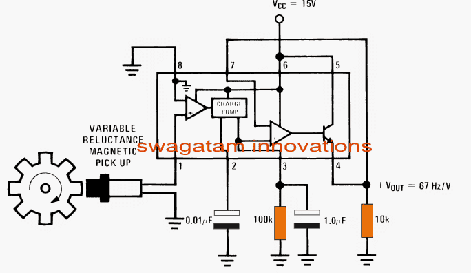
Now if we look at the simple speedometer circuit diagram below then we can clearly see that IC LM2907 is sitting right at the center of the setup. This IC is the main guy here and does the main job of detecting and converting the frequency.
How the Circuit Works
So when we open and look inside this LM2907 IC then we find that it has some important internal sections. First there is a differential comparator at the input side. Then after that, there is a charge pump stage. After that we have an opamp buffer, and finally an emitter follower amplifier stage at the output.
Pin number 1 of the IC is where we give the frequency signal input. This pin is like the tachometer input, and it takes the magnetic pickup signal. That signal comes as changing electrical pulses caused by a magnet passing near a coil.
The differential opamp inside compares this signal with its other input which is connected to ground. It can catch even very small pulses at pin number 1 and makes them stronger, which means it amplifies them.
Then comes the charge pump stage. What this stage does is, it grabs those amplified signals and keeps holding and pumping them properly. It does this in such a way that when the frequency keeps going higher, then the output from the IC also keeps increasing properly and proportionally. So, the higher the frequency, the more voltage we get at the output.
This whole charging and pumping action is managed by the capacitor connected at pin number 2 and the resistor at pin number 3 of the IC.
Then the final voltage that comes out which is boosted and proportional to the input frequency, passes through an emitter follower transistor. After that it appears across a 10k resistor which is at the output side.
From the circuit diagram we can understand that the sensitivity of the output is around 1 volt for every 67 hertz. That means if frequency becomes 67 plus 67 is equal to 134 hertz then output will be 2 volts. If frequency keeps rising more, then voltage will also keep going up in a straight-line manner.
How to Calculate the Output Voltage
Now if we want to calculate and find the exact output voltage, then we can use a very simple formula which is:
VOUT = fIN × VCC × Rx × Cx
Here Rx is the resistor connected at pin number 3 and Cx is the capacitor connected at pin number 2 of the IC.
We can directly see and read this output voltage by connecting a moving coil analogue voltmeter across the 10k resistor. The needle will show the voltage which tells us about the frequency.
For making the magnetic pickup part of this speedometer circuit, we can take a small ferrite ring and wind around 50 turns of 30 SWG wire on it. This becomes the coil part.
Then on the wheel which we want to measure speed or RPM from, we should fix a small magnet on the rim. The size of the magnet should be proper so that every time the wheel rotates one time then the magnet comes in front of the coil one time. This creates one electrical pulse for every full rotation, which the IC catches and processes.
Circuit Diagram
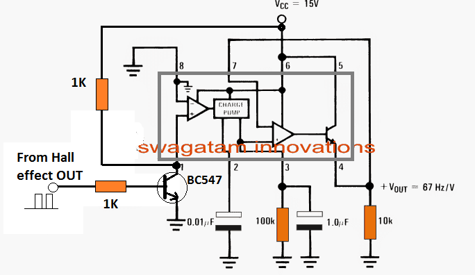
An extra BJT stage may be introduced to pin 1 of the IC, as seen below, to deliver the appropriate frequency sensing in the event a hall effect sensor is to be used as the sensor.
Construction Procedures:
We First Make the Magnetic Pickup Coil
So first thing we need is that magnetic coil sensor part. For this we take one small ferrite ring core like those round black rings used in circuits. Then we wind around 50 turns of 30 SWG enamelled copper wire tightly on it. We must make the winding neat and close together. After winding we solder two flexible wires at both ends of the coil so we can connect it on the board later. This coil will behave like our variable reluctance pickup. It will create electric pulses whenever a magnet goes near it.
Then We Fix the Magnet on the Wheel Rim
Now we take the wheel which we want to check RPM or speed from. We stick one strong small magnet on the rim area of the wheel. We must stick it in such a way that when the wheel rotates once then this magnet passes exactly in front of the coil only one time. The magnet must come face to face with the pickup coil in every full rotation. We should not keep too much gap between magnet and coil. Maybe around 2 to 5 mm gap is acceptable.
Now We Fix the LM2907 and Other Parts on a PCB
So next we take a general purpose PCB board and fix the LM2907 IC in the middle part of the board. It is better if we use one 8-pin IC base so that we can remove or replace the IC easily later. Then we take all the resistors and capacitors shown in the diagram and solder them one by one in correct positions
First we connect one 0.01 microfarad capacitor from pin number 1 to ground
Then we take one 100k resistor and connect it between pin number 3 and ground
Next we solder one 1.0 microfarad capacitor from pin number 4 to ground
Also one more 1.0 microfarad capacitor is connected from pin number 2 to ground
And at the output side we place a 10k resistor from pin number 4 to ground. This acts like the load resistor where we measure the voltage
We Connect the Power Supply Wires
Now we give power to the IC. We connect the positive 15V supply wire to pin number 6. All the ground connections at pin 2 pin 4 pin 8 and all component grounds must be joined together and connected to the negative of the 15V supply.
We Connect the Pickup Coil Wires to the IC
Now we take the two ends of our magnetic coil that we made in step one. We connect one wire to pin number 1 of the IC. The other wire goes to ground. This sends the magnetic pulses to the IC whenever the magnet on the wheel passes the coil.
Finally We Connect the Output Meter
After everything is connected properly now we want to measure the output voltage. So we connect one analogue voltmeter moving coil type across the 10k resistor at the output. That meter will show us how much voltage is generated. This voltage tells us the frequency of rotation of the wheel. We can also use a digital voltmeter if we want.
For Hall Effect Sensor Integration
Leave a Reply