The explained bass treble tone controller circuit not only facilitates the control of the bass, treble frequencies but also the mid range frequencies using its efficient 3 way tone control circuit providing an excellent custom music output as preferred by the user.
Using a Single Transistor
We will begin with a rather simple bass treble controller circuit using a single BC547 transistor as shown below.

Although simple, yet this little tone control circuit can provide a reasonably impressive bass and treble responses. The bass boost is created by enhancing all frequencies below 100 Hz at the maximum setting, while the treble response is created by cutting all frequencies below 500 Hz, at the maximum treble setting.
Using Op amps
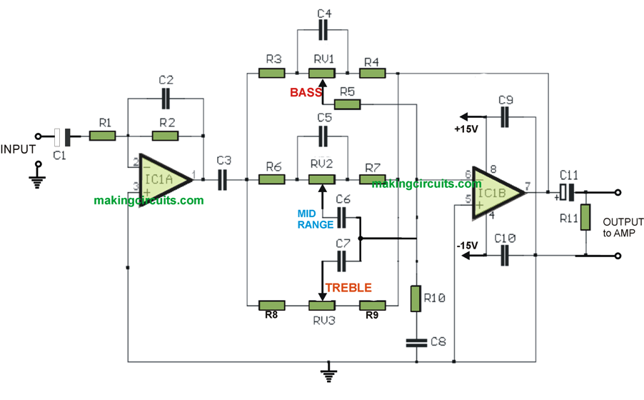
As shown in the next figure below the circuit employs opamps for the processing and generates an excellent qulity sound as per the taste of the listener and enable tailored frequency music output which results in enriching even an ordinary piece of music input.

The discussed bass, treble tone controller circuit thus effectively performs like a 3 band graphic equalizer circuit allowing the user with distinct 3 way control of the sound frequency.
The bass control basically allows only the lower range of the frequency, ideally between 10Hz and 300Hz, that means the user can adjust this pot to cut off all frequencies that might be within or beyond this frequency range.
The treble control can be considered just the opposite of bass, and this control allows the user to trim the input frequency within the range of 2kHz and 6kHz, which implies that the user can use this pot to tailor the frequency anywhere between this range.
Now obviously, the mid range control has the ability to provide the facility of adjusting frequencies between the above discussed 300Hz and 2kHz.
With all the 3 controls, the this simple bass treble mid range tone controller circuit becomes a full fledged 3 way graphic equalizer circuit which enables the users to adjust the 3 control as per their personal taste such that the most pleasant hearing sensation is achieved for the listener.
Parts List
| R1-R2= 47K | C1-C11= 10uF/25V | C8= 1.2nF MKT |
| R3-R4-R5-R12-R13= 10K | C2= 33pF | C9-10= 100nF 63V MKT |
| R6-R7= 3.3K | C3= 2.2uF/25V MKT | C12=47uF 25V |
| R8-R9= 1.8K | C4= 47nF/25V MKT | RV1-RV2= 100Kohms Lin. |
| R10= 270 ohms | C5-C7= 4.7nF/25V MKT | RV3= 470Kohms Lin. |
| R11= 22K | C6= 22nF/25V MKT | IC1= TL072, NE5532 |
Hi-Fi Bass, Treble, Presence Tone Control Circuit
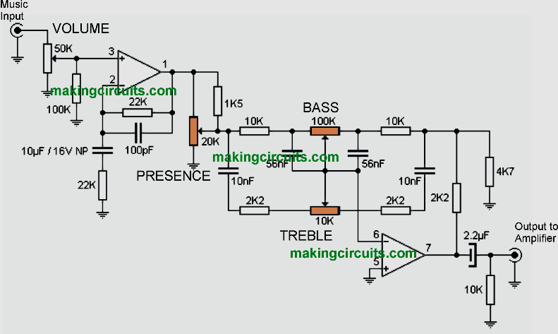
In this post we learn how to make a simple yet Hi-Fi super tone control circuit featuring adjustable bass, treble, and presence control circuit using potentiometers and processed using opamps.
This specific tone control features a couple of control knobs or pots which enable you to vary the presence of bass and treble within an music transmission.
A high-end integrated circuit for sound processing is employed made up of 2 operational amplifiers inside pickup.
This is the NE5532, which can be run with +/- 15V.
The 50K potentiometer on the input determines the input level or level of sensitivity of the process. The 20K preset must be initially be positioned within the middle of your pots dial.

If you find a distortion content or deformation inside the music, cut down the adjustment right up until a dedicated processing is accomplished.
The 100K potentiometer sets the quantity of bass, whilst the 10K potentiometer executes exactly the same for the treble response.
Since the power supply for this simple Hi-fi bass, treble, presence tone control circuit is actually symmetrical at the port 4 of the integrated (GND marked in the image above) it ought to connect with -15V while terminal 8 (designated as Vcc) needs to go to + 15V. The body should be assembled to 0V, that the integrated will not hook up with over to the non-inverting input of the operational 2nd (port 5).
Stereo Bass Treble Control with Preamplifier Circuit
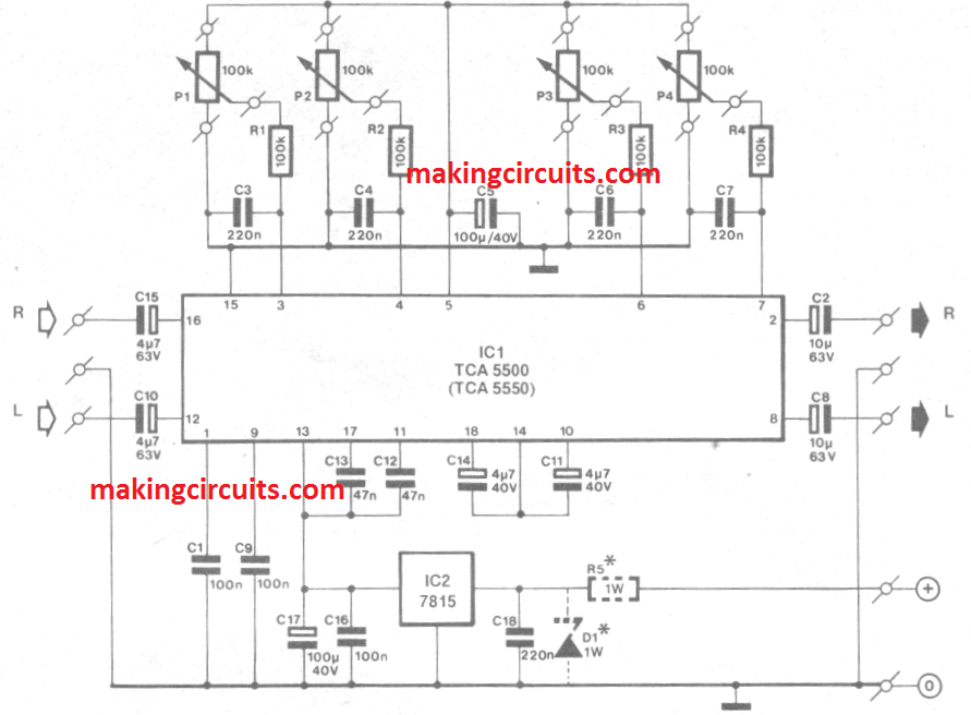
This simple, one-chip, stereo preamplifier is ideal for build-ing into an existing AF power amplifier. It is based on a recently introduced integrated circuit, the Type TCA5500 or TCASSSO from Motorola.
This double AF amplifier chip with inputs for balance, volume, and bass and treble controls forms a sound basis for a good quality preamplifier with a minimum of components.
The onset points for the bass and treble controls are defined with Ca and C4 respectively.
All (mono) potentiometers are best fitted direct onto the circuit board to make for simple mounting into a cabinet, and also to prevent hum and noise being picked up in the wiring that would otherwise be required.
The preamplifier has a current consumption of 35 mA, of which S mA is drawn by voltage regulator IC2. Zener diode D1 and power resistor R5 should be added if the positive supply voltage available in the power amplifier is more than about 30 V .


High Quality Tone Control Circuit
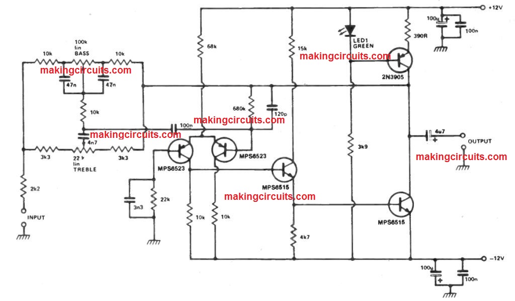
When constructing a superior quality preamp, the creator was confronted by the situation of creating an appropriate high quality tone control circuit stage.
Op amps including the 741 are generally utilized, however in common possess a bad slew rate, relatively higher distortion and high noise when utilized in this application.
The high quality tone control circuit revealed is dependent on an inverting op amp employing discrete transistors to get over these difficulties.

The output stage is influenced with a regular current source, biased with a green LED to offer temperature compensation.
Using the controls flat the unit supplies unity gain, therefore the stage could be turned in or out.
The layout is appropricate for inputs amongst 100 mV and IVO and supplies the best overload margin at low distortion for the precise processing of transients.
The normal screening measures towards hum needs to be performed.
In 2nd figure you didn’t mention C12 but spare parts list you have mentioned it . Please tell me the position of C12 . In 2nd figure you have mentioned pin number 2 is positive input of ic NE 5532 but in 3rd figure you have mentioned pin number 3 is the positive input of ic NE 5532 . Please tell me what is correct .
Sorry for the confusion, I would suggest your to strictly follow the schematic only, and ignore the text section…
Sy akan merakitnya
What is MKT capacitor sir