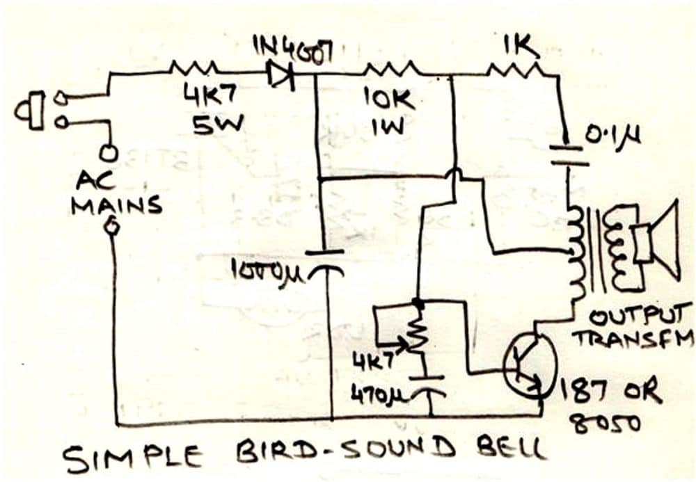
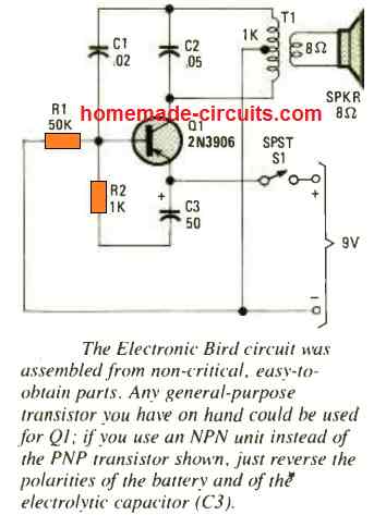
This image shows a basic circuit that makes a chirping bird sound. It uses everyday parts, like a small transformer you'd find in a portable radio.
How it works:
The circuit uses a transistor and a tiny transformer to create this loop.
Regular house current comes in, a resistor (4K7) tones it down for the circuit's DC side.
A diode flips the AC current to DC, and a capacitor smooths it out.
This smoothed DC reaches the transistor's base, which turns it on. When the transistor is on, it connects one coil of the transformer to ground.
This grounding cuts off the voltage going to the transistor, so it switches off.
The transformer, due to this on-off action, generates a voltage pulse that gets pushed back to the other coil.
When the transistor is off, the base voltage recovers, and the whole process starts again.
These ongoing pulses in the transformer create a strong electrical pressure (EMF) that gets amplified by the loudspeaker, making the chirping sound.
This circuit uses a combination of a 10k resistor and a 0.1uF capacitor to control the transistor's feedback loop.
By turning the 4.7kΩ potentiometer, you can adjust the frequency of the chirping sound along with another 0.1uF capacitor. These adjustments help you fine-tune the exact tone of the bird chirp to achieve the desired effect.
Keep this circuit unplugged while handling it! Direct connection of this circuit to the mains AC voltage is exceedingly risky and has the potential to result in fatalities or major injuries. Work on the circuit only when it is fully unplugged, and proceed with great caution.
Parts List
- Resistors
- 4.7 k 5 watt = 1
- 10 k 1 watt = 1
- 1 k 1/4 watt = 1
- preset, trimpot 4.7 k = 1
- Capacitors
- 1000 µF, 50 V = 1
- 470 µF, 25 V = 1
- Ceramic Disc 0.1 µF = 1
- Transistor 8050 = 1
- Audio Output Transformer = 1
- Push button = 1
Making the bird chirp:
This circuit can create very realistic bird sounds! It has a control knob that lets you change the pitch of the chirp from low to high frequencies. The size of the speaker (ideally 4 to 6 inches and placed in the same enclosure) also affects the overall sound quality.
Behind the chirp:
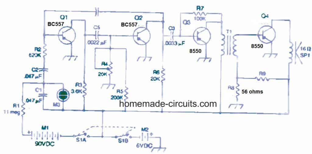
Technically, this circuit is a type of oscillator called a free-running multivibrator. By turning a knob labeled "R4," you can adjust the frequency of the chirp between 1,000 and 10,000 Hertz (Hz).
The secret to the bird-like sound comes from a separate low-frequency oscillator circuit that uses a neon bulb (M3). This circuit creates a signal that controls transistor Q1. Interestingly, if you remove capacitor C1, the chirping effect disappears, and the circuit becomes a regular variable-frequency multivibrator. Transistors Q3 and Q4 play a role in amplifying and outputting the final signal.
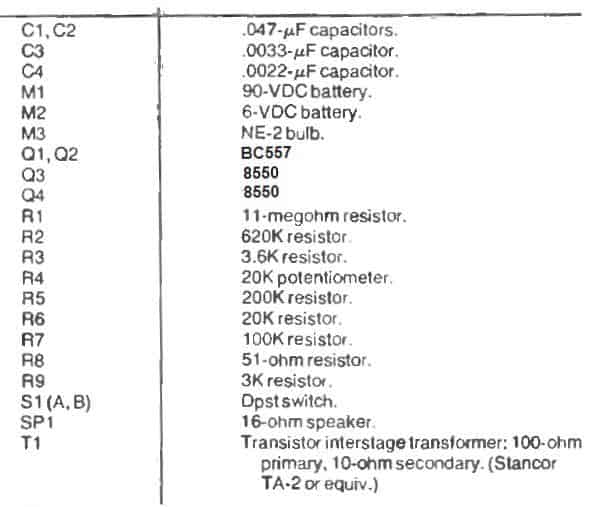
Parts List
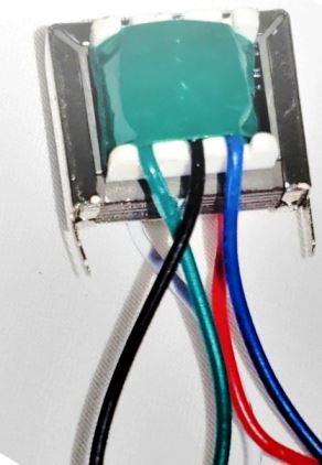
You can any standard audio output transformer as shown below, for T1:
Another Simple Bird Sound Generator
Bringing Bird Sounds to Life: How This Simulator Works
This bird sound simulator is like a mini-orchestra for bird noises! It uses three special circuits called relaxation oscillators, along with a "decade counter."
Each relaxation oscillator is a type called an astable multivibrator. These clever circuits use chips called CMOS logic inverters (AMV1 to AMV3) to create their own unique rhythms.
AMV1 is particularly interesting because it generates a very slow pulse, just a fraction of a hertz (cycle per second). This slow pulse acts like a conductor's baton, telling the decade counter chip (IC2) how fast to keep track of the beat.
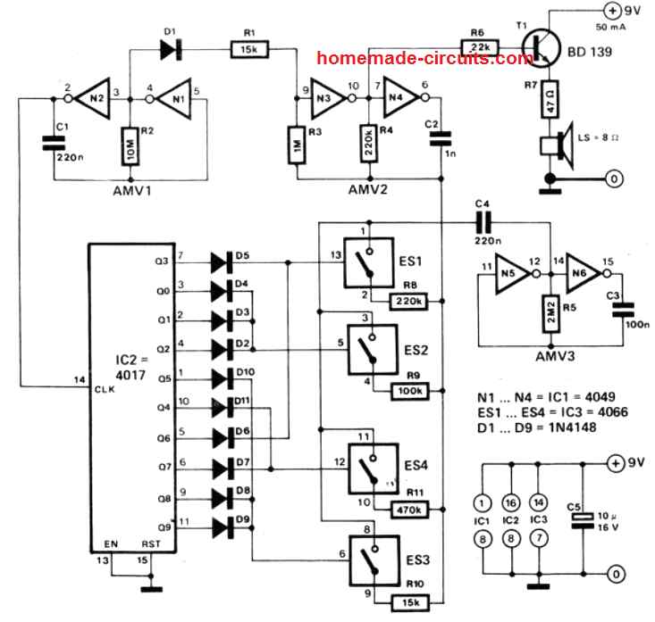
In accordance with clock pulses, logic 1 traverses outputs Q0 through Q9 when the counter is in operation.
The AMV2 oscillator uses a high-frequency note to simulate bird vocal chords.
When modulating the AMV2 output, the AMV3 oscillator offers a variety of frequencies.
Unlike synthetic chimes, this system accurately replicates the sounds of live birds.
Resistance between C4 and R4 determines the frequency from AMV3.
To be more precise, a resistor flips between R8 and R11.
Using counter outputs, CMOS changes the ES1 to ES4 control resistor switching.
This configuration guarantees sporadic emission, more akin to actual birds than repetitive noise.
The circuit provides several ways to customize the sound of the bird.
To get desired bird sound effects, modify the values of the resistors (R8-R11), counter outputs, and switch connections (ES1-ES4).
Leave a Reply