• Skip to main content
  • Skip to primary sidebar

Making Easy Circuits

Learn and build electronic circuits

You are here: Home / Voltage Regulators / Simple Boost Converter Circuit

Simple Boost Converter Circuit

Last Updated on January 10, 2018 by Admin 4 Comments

A very simple boost converter circuit can be built by using a handful of transistors and some passive electronic components for boosting any low voltage to the desired high voltage level.


simple boost converter circuit


The shown boost converter circuit is simple with its topology since it works with a couple of standard circuits stages involving an transistorized astable stage and a boost converter stage.

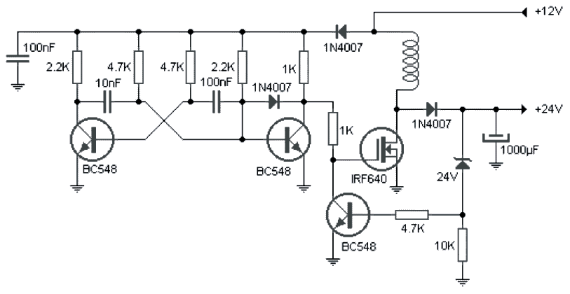
The astable stage is formed by the two BC548 transistors and the associated resistors and capacitors. The involved two capacitors and the two base resistors determine the frequency of the astable

This frequency is fed to the gate of a mosfet which is rigged as a boost converter in conjunction with its drain inductor.

The astable frequency drives the mosfet and inductor at the specified frequency causing a much higher stepped up voltage to develop across the drain and source of the mosfet.

This boosted voltage is collected across the 1000uF filter capacitor after appropriately rectifying it via the 1N4007 diode.

The number of turns on the coil could be equal to the supply voltgae level, here it's around 12 turns, diameter could be around 20mm. The core should be a ferrite material.

The feedback BC548 makes sure that ther boost volatge should not increase above 24V which is determined by the 24V zener diode.

This implies thsat the proposed simple boost converter circuit output could be dimensioned as per user's choice simply by increasing the number of turns and/or by altering the value of the 24V zener diode.

You'll also like:

  • 1.  2000 watts Heater Controller Circuit
  • 2.  High Power Triac Dimmer Circuit for 1000 watt Loads
  • 3.  12V to 24V Voltage Doubler Circuit using IC 4093
  • 4.  High Current LM317 Variable Power Supply Circuit
  • 5.  3V to 110/220V Converter Circuit
  • 6.  Voltage Stepper Circuit or Voltage Booster Circuit

About Admin

Hey friends, Thanks a bunch for stopping by this site! I am an engineer with a Bachelor of Engineering in Electronics and Telecommunication. One of my passions is gathering information from all sorts of electronics books and tutorials. I then take that information and compile it into a language that is super easy to understand. My goal is to make those complex electronics circuit concepts and technical terms much more accessible for all the new and budding electronics engineers out there. I can also design customized circuit diagrams as required by the users.
If you have any questions related to this field, please do not hesitate to drop a comment! I am always here and ready to help you out with any queries you might have. I cannot wait to hear from you!

Reader Interactions

Comments

  1. Sagar says

    September 26, 2023 at 6:10 pm

    Very nice circuit

    Reply
    • admin says

      September 26, 2023 at 6:25 pm

      Thank you!

      Reply
  2. Ivan says

    May 17, 2023 at 3:43 pm

    There is a mistake in schematic – the Base of the middle BC548 must not be connected to junction of 100nF, 2.2k and 1N4007. Please remove this vertical wire from scheme. After this, the circuit works fine, I have built it and tested.

    Reply
    • admin says

      May 20, 2023 at 10:05 am

      Thank you, you are correct, that seems to be a drawing mistake.

      Reply

Leave a Reply Cancel reply

Your email address will not be published. Required fields are marked *

Primary Sidebar

Categories

  • 3 Phase (4)
  • 8051 Microcontroller (1)
  • Arduino (11)
  • Audio and Amplifier (102)
  • Automation (8)
  • Battery Chargers (64)
  • Bicycle Projects (4)
  • Car and Motorcycle Projects (39)
  • Datasheets (10)
  • DIY Projects (5)
  • Electrical (15)
  • Free Energy (6)
  • Games Projects (2)
  • High Voltage (14)
  • Hobby Projects (30)
  • Household Circuits (2)
  • IC 555 Circuits (5)
  • Ignition Circuits (2)
  • Indicators (50)
  • Infrared (6)
  • Inverter Circuits (29)
  • Lights and Lamps (97)
  • Medical (8)
  • Meter and Tester Circuits (38)
  • Motor Driver (17)
  • New Circuits (56)
  • Oscillators (30)
  • Pets and Pests (5)
  • Power supply (80)
  • Protection Circuits (25)
  • PWM (9)
  • Remote Control (20)
  • Security and Alarm Circuit (48)
  • Sensors and Detectors (66)
  • Signal Processor (23)
  • Solar Controller Circuits (62)
  • SSR (3)
  • Temperature Controller (20)
  • Timer (25)
  • Transformerless (7)
  • Transmitters (12)
  • Tutorials (45)
  • UPS (2)
  • Voltage Regulators (57)
  • Water Sensor and Controller (29)
  • Home
  • Privacy Policy
  • Contact
  • Disclaimer
  • Copyright

© 2025 · Making Easy Circuits